


27
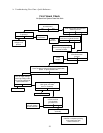
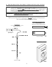
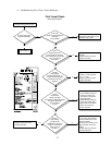
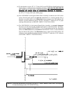
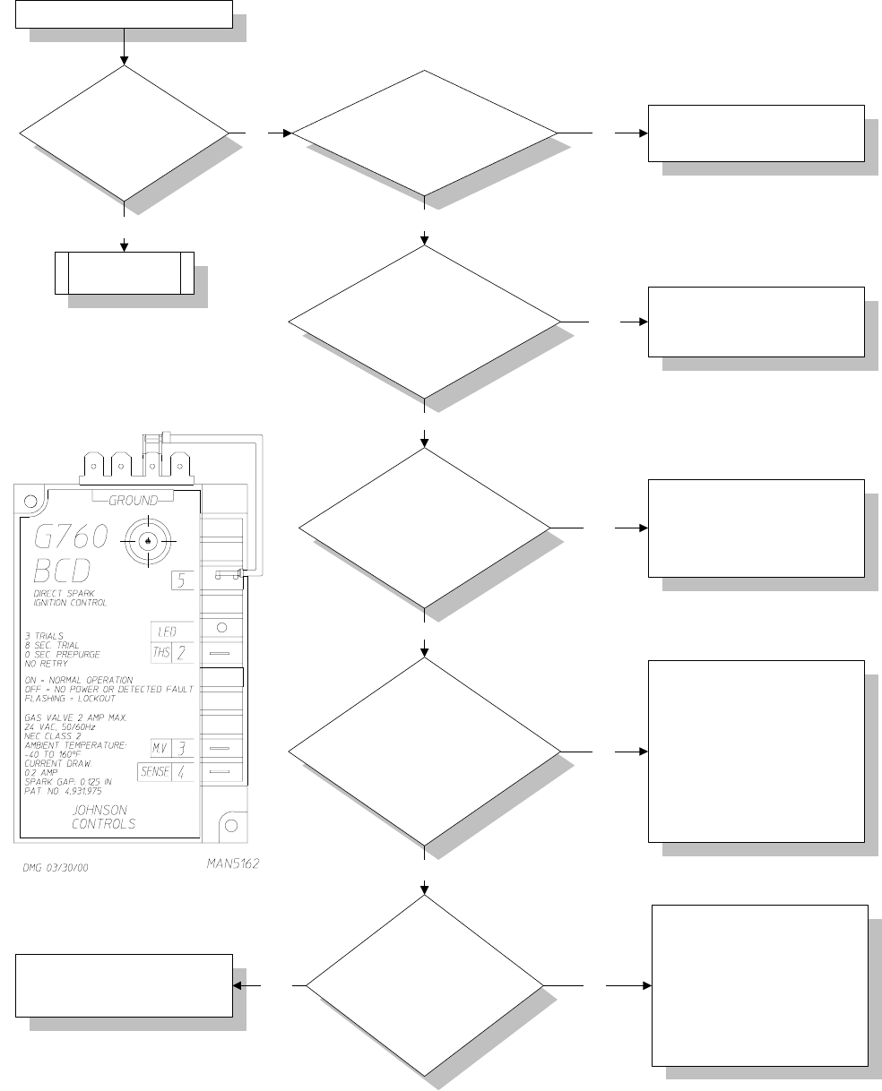
First Visual Check
(Does Ignitor Spark?)
I
s spark evident (on)
at Ignitor Assembly?
Is 24 Volts
present across DSI Module
terminals
TH and COM?
Check
High Voltage (HV)
Lead for nicks or cracking,
where sparking to ground may
occur. Is this wire
damaged?
Go To Chart 2
Open circuit to DSI System.
Check the 24 VAC power source
Sail Switch and Hi-Limit
.
Yes
No
Yes
No
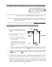
Visually
inspect High
Voltage (HV) Wire
connections at both DSI Module
and Ignitor Assembly.
Are connections
secure?
Visually
inspect Spark
Electrode Assembly. Is
ceramic cracked or Spark
Electrode incorrectly
gapped?
No
No
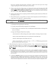
Remove
High Voltage
(HV) Wire from
DSI Module and visually
inspect. Is conductor
visible at end of
HV Wire?
Yes
Repair or replace HV Lead
Assembly.
Energize system and check
for proper operation.
If cracked, replace Electrode
Assembly. Correct gap size
is 1/8" (+/- 1/32").
Energize system and check
for proper operation.
1. At DSI Ignitor Assembly be
sure HV Wire is secure in
the boot as well as the
connection to the Ignitor
Probe Assembly.
2. At DSI Module, center the
end of the HV Wire with a
Spike Terminal. Energize
system and check for
proper operation.
Cut the end off of the HV Wire
1/4" at a time until conductor
becomes visible and is flush
with the insulation.
Reconnect the HV Wire to the
Spike Terminal on the DSI
Module.
Energize system and check
for proper operation.
Yes
Yes
No
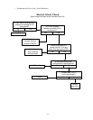
Computer/Timer Calls For Heat
Replace the DSI Module.
Energize system and check
for proper operation.
NoYes
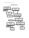
d. Troubleshooting Flow Chart - Quick Reference...