


55
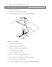
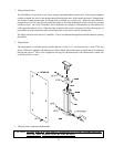
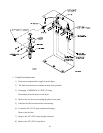
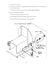
10) Remove the two (2) 3/8 (9.525 mm) mufflers. (Refer to the illustration on page 56.)
Reinstall these mufflers on the new solenoid valve body.
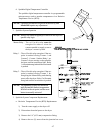
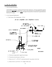
11) The left orifice (marked #12 on the tilting solenoid valve) now must be configured for external pilot.
NOTE: For 1-Way Tilt models proceed to Step #23.
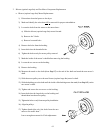
12) Remove the two (2) Phillips head screws.
13) Carefully remove the end of the valve.
NOTE: The pieces within the end of the valve are small. Handle carefully to avoid losing parts.
14) Place the solenoid plug over the pilot orifice position of the solenoid valve end.
15) Place the O-ring (from Step #13) into the top portion of the solenoid valve end.
16) Place end back onto the valve removed in Step #13.
17) Replace the two (2) Phillips head screws removed in Step #12.
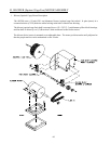
18) Remove Allen plug on the left side of the orifice marked #12 on the tilting solenoid valve.
19) Remove the pilot airs 1/4 (6.35 mm) compression fitting.
20) Remove the pilot airs 1/8 (3.175 mm) elbow.
Reinstall the elbow onto the new solenoid valve body.
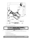
21) Reconnect the three (3) air lines removed in Step #7.
Tighten/secure compression fittings on the air lines loosened in Step #7.
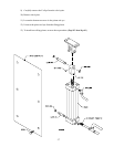
22) Bolt the solenoid valve in place using the two (2) 1/4-20 hex head bolts removed in Step #8.
23) Reconnect the three (3) air line compression fittings.
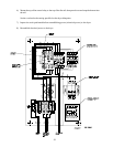
24) Reestablish the compressed air supply to the dryer.
25) Check for leaks.
26) Reestablish electrical power to the dryer.
27) Engage EMERGENCY STOP (E-Stop) disengaged in Step #3.