94 Rockwell Automation Publication 2097-UM002C-EN-P - December 2013
Chapter 5 Configure and Start Up the Kinetix 350 Drive System
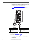
5.
6.
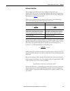
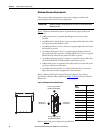
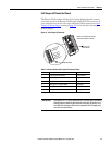
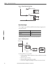
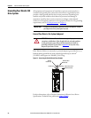
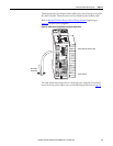
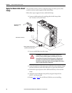
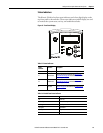
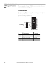
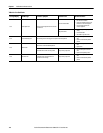
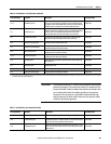
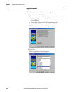
7. Observe the status indicator on the front of the Kinetix 350 drive.
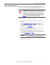
Test and Tune the Axes
This procedure assumes that you have configured your Kinetix 350 drive, your
ControlLogix EtherNet/IP controller, and applied power to the system.
For help using Logix Designer Application as it applies to testing and tuning your
axes with ControlLogix EtherNet/IP controller, refer to
Additional Resources on
page 10.
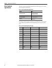
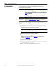
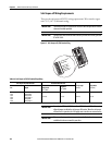
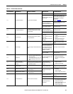
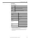
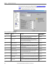
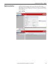
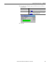
Test the Axes
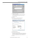
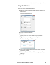
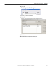
Follow these steps to test the axes.
1. Verify the load was removed from each axis.
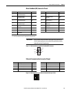
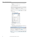
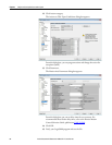
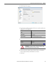
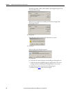
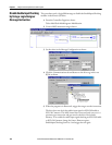
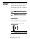
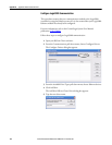
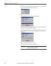
2. Right-click an axis in your Motion Group folder and choose Properties.
The Axis Properties dialog box appears.
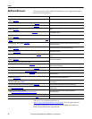
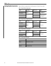
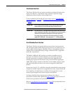
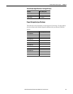
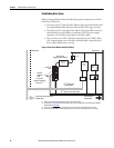
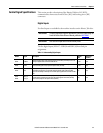
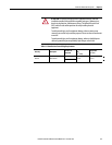
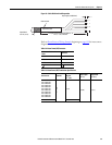
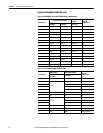
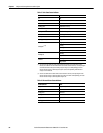
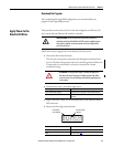
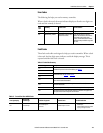
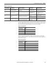
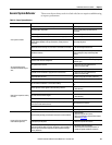
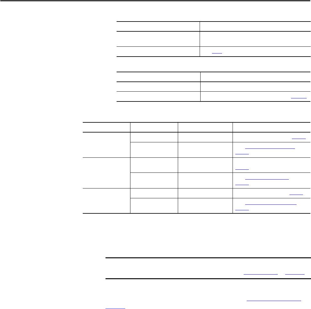
If Your Logic Power Then
Is from (24V DC) back-up power
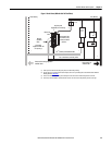
Apply 120, 240, or 460V AC mains input power to the drive (IPD
connector)
Mains input power Go to step 5
If drive ENABLE is Then
Hard wired Apply 24V DC
Not used Disable enableInputChecking by using procedure on page 100
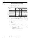
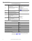
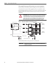
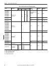
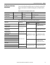
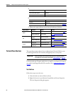
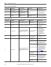
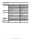
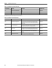
Status Indicator Condition Status Do This
Module
Steady green Operational condition Observe the Axis, status indicator page 79
Steady or flashing red Drive is faulted
Go to Module State Status Indicator on
page 79
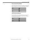
Axis
Steady green or amber,
flashing
Operational condition
Observe the Network, status indicator
page 79
Steady or flashing red Axis is faulted
Go to Axis State Status Indicator on
page 80
Network
Steady green Communication is ready Go to Test and Tune the Axes on page 94
Any state other than
steady green
Communication error
Go to Network State Status Indicator on
page 80
Before proceeding with testing and tuning your axes, verify that the drive
status indicators are operating as described in
Status Indicators on page 119.