30 Rockwell Automation Publication 2097-UM002A-EN-P - December 2013
Chapter 2 Install the Kinetix 350 Drive System
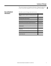
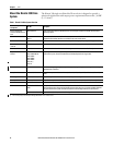
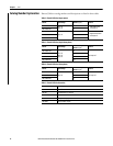
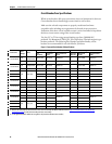
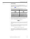
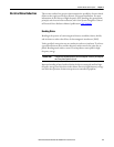
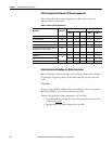
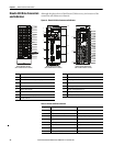
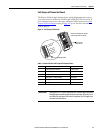
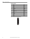
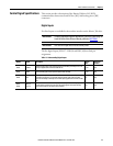
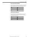
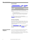
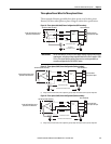
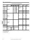
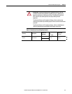
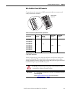
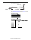
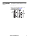
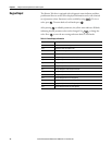
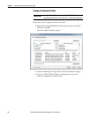
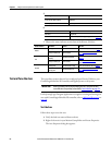
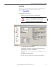
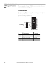
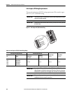
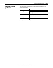
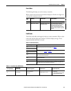
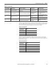
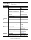
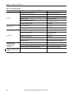
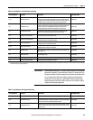
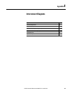
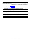
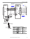
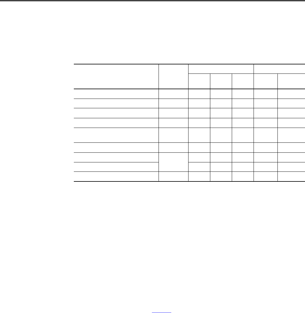
Cable Categories for Kinetix 350 Drive Components
These table indicate the zoning requirements of cables connecting to the
Kinetix
350 drive components.
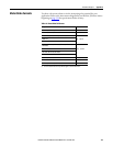
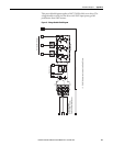
Table 9 - Kinetix 350 Drive Components
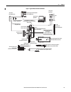
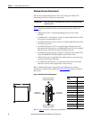
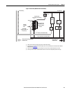
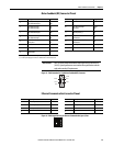
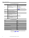
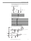
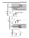
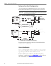
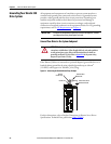
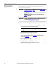
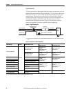
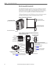
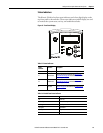
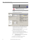
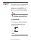
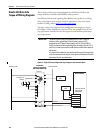
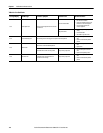
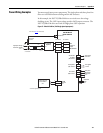
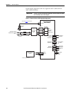
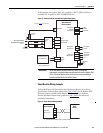
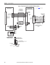
Noise Reduction Guidelines for Drive Accessories
Refer to this section when mounting an AC line filter or shunt resistor module
for guidelines designed to reduce system failures caused by excessive electrical
noise.
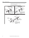
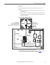
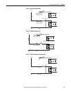
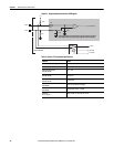
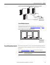
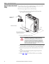
AC Line Filters
If you are using a Bulletin 2090 line filter, mount the filter on the same panel as
the Kinetix
350 drive, and as close to the drive as possible.
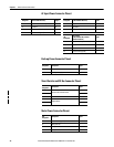
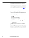
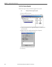
Observe these guidelines when mounting your AC line filter:
• Good HF bonding to the panel is critical. For painted panels, refer to the
examples on
page 26.
• Segregate input and output wiring as far as possible.
Wire/Cable Connector
Zone Method
Very
Dirty
Dirty Clean
Ferrite
Sleeve
Shielded
Cable
L1, L2, L3 (unshielded cable) IPD X
U, V, W (motor power) MP X X
B+-, B-, BR (shunt resistor) BC X
24V DC BP X
Control COM, 24V DC control, safety enable, and
feedback signals for safe-off feature
STO X
Motor feedback MF X X
Registration
IOD
X X
Others X
Ethernet Port 1 X X