52 Rockwell Automation Publication 2097-UM002C-EN-P - December 2013
Chapter 4 Connect the Kinetix 350 Drive System
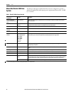
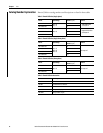
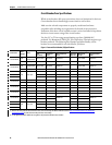
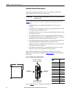
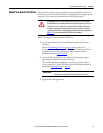
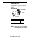
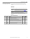
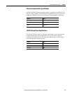
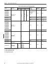
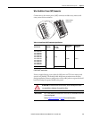
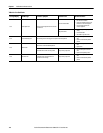
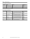
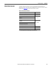
Recommended Cables
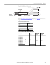
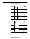
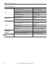
The Motor Power Cable Compatibility table on page 66 and Motor Feedback
Cables for Specific Motor/Feedback Combinations table on page 71 show the
cables Rockwell Automation recommends you use with the Kinetix 350 drive.
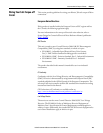
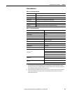
If it is necessary for you to build or modify your own cable, follow these
guidelines:
• Connect the cable shield to the connector shells on both ends of the cable
with a complete 360° connection.
• Use twisted pair cable whenever possible. Twist differential signals with
each other and twist single-ended signals with the appropriate ground
return.
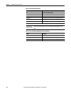
Refer to the Kinetix Motion Control Selection Guide, publication
GMC-SG001, for low-profile connector kit, drive-end (mating) connector kit,
and motor-end connector kit catalog numbers.
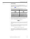
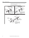
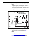
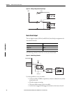
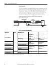
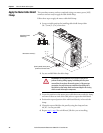
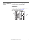
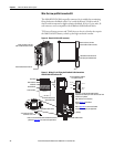
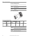
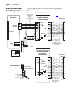
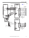
Route Power and Signal Wiring
Be aware that when you route power and signal wiring on a machine or system,
radiated noise from nearby relays, transformers, and other electronic drives can be
induced into motor or encoder feedback signals, input/output communication,
or other sensitive low voltage signals. This can cause system faults and
communication anomalies.
Refer to Electrical Noise Reduction on page 25 for examples of routing high and
low voltage cables in wireways. Refer to the System Design for Control of
Electrical Noise Reference Manual, publication
GMC-RM001, for more
information.
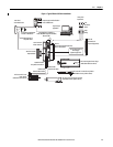
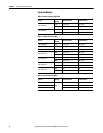
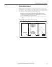
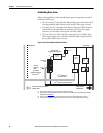
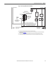
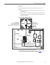
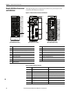
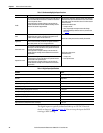
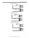
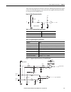
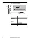
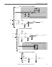
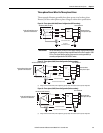
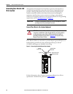
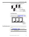
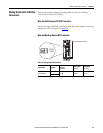
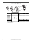
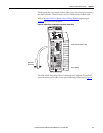
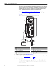
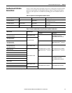
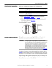
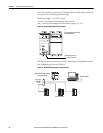
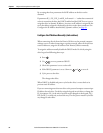
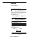
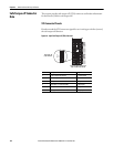
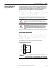
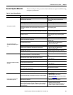
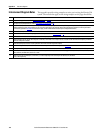
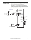
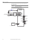
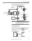
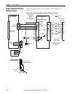
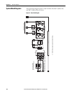
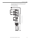
Determine the Input Power
Configuration
This section contains examples of typical single-phase and three-phase facility
input power wired to single-phase and three-phase Kinetix
350 drives.
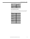
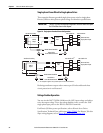
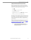
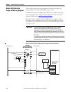
The grounded power configuration lets you ground your single-phase or three-
phase power at a neutral point. Match your secondary to one of the examples and
be certain to include the grounded neutral connection.
Factory-made cables are designed to minimize EMI and are recommended over
hand-built cables to optimize system performance.