Rockwell Automation Publication 2097-UM002C-EN-P - December 2013 47
Kinetix 350 Drive Connector Data Chapter 3
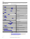
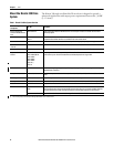
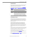
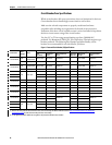
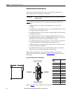
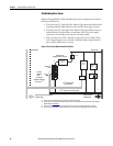
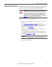
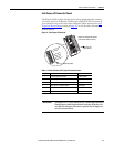
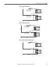
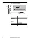
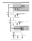
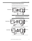
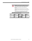
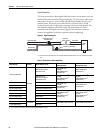
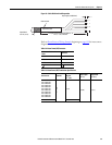
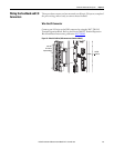
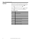
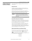
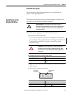
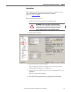
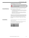
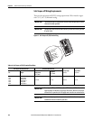
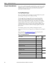
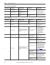
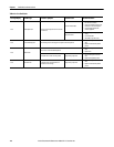
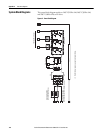
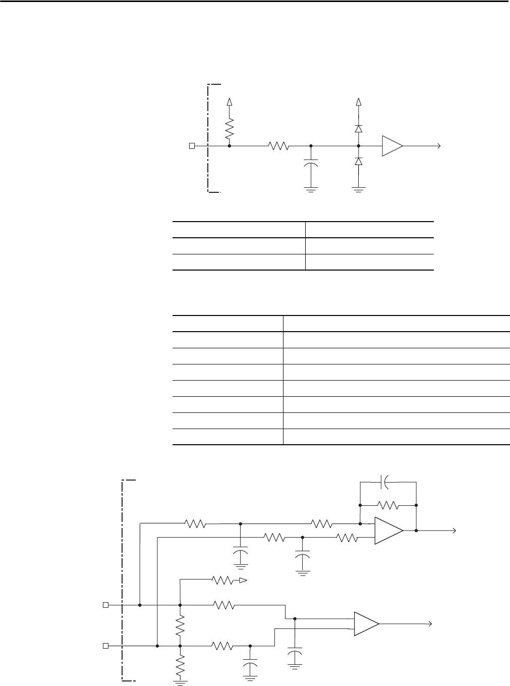
This is the motor thermostat interface schematic. Although the thermostat signal
is shown for all feedback types, some motors do not support this feature because
it is not part of the feedback device.
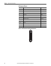
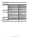
Figure 20 - Motor Thermostat Interface
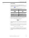
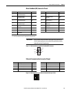
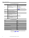
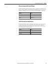
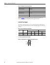
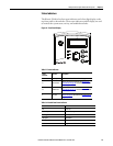
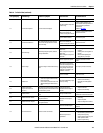
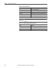
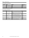
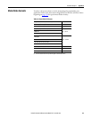
Table 17 - Motor Thermostat State Specifications
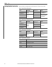
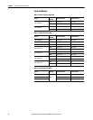
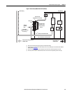
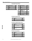
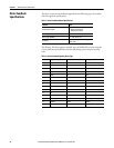
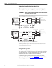
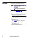
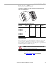
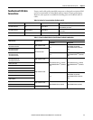
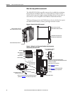
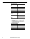
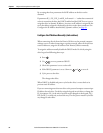
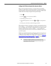
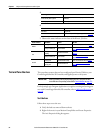
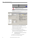
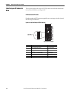
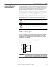
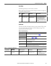
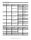
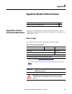
Table 18 - Stegmann Hiperface Specifications
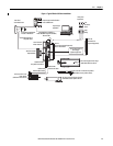
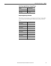
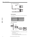
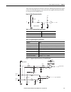
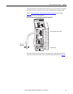
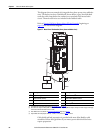
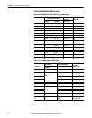
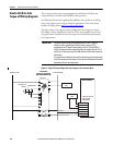
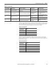
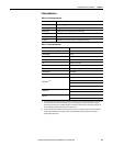
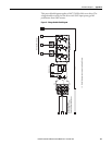
Figure 21 - Stegmann Hiperface Interface, SIN and COS Signals
+5V
1 k
Ω
6.81 k
Ω
0.01 μ
F
TS
+5V
State Resistance at TS
(1)
(1) Resistance is measured between TS (MF pin 11) and ECOM (MF pin 6)
No Fault 500 Ω
Fault 10 kΩ
Attribute Value
Protocol Hiperface
Memory support Not programmed, or programmed with Allen-Bradley motor data
Hiperface data communication RS485, 9600 bps, 8 data bits, no parity
Sine/Cosine interpolation 2048 counts/sine period
Input frequency (AM/BM) 250 kHz, max
Input voltage (AM/BM) 0.6...1.2V, p-p, measured at the drive inputs
Line loss detection (AM/BM) Average (sin
2
+ cos
2
) > constant
56 pF
SIN+ or
COS+
SIN- or
COS-
+
1 k
Ω
-
to AqB Counter
1 k
Ω
10 k
Ω
10 k
Ω
1 k
Ω
1 k
Ω
1 k
Ω
56 pF
56 pF
26.7 k
Ω
47 pF
to A/D Converter
56 pF
+5V
1 k
Ω
+
-
1 k
Ω