62 Rockwell Automation Publication 2097-UM002C-EN-P - December 2013
Chapter 4 Connect the Kinetix 350 Drive System
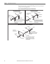
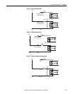
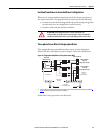
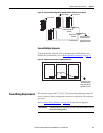
Wiring Guidelines
Use these guidelines as a reference when wiring the connectors on your
Kinetix
350 drive power modules.
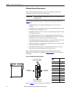
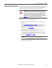
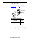
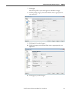
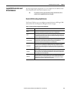
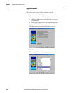
Follow these steps when wiring the connectors on your Kinetix 350 drive
modules.
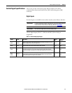
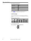
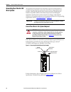
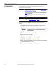
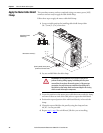
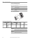
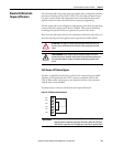
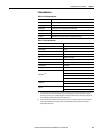
1. Prepare the wires for attachment to each connector plug by removing
insulation equal to the recommended strip length.
2. Route the cable/wires to your Kinetix 350 drive.
3. Insert wires into connector plugs.
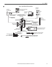
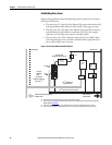
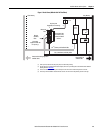
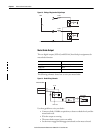
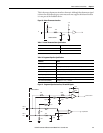
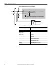
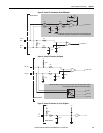
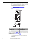
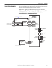
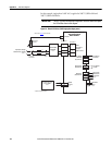
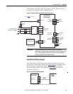
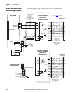
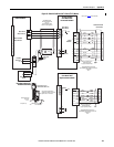
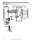
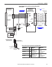
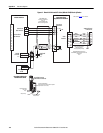
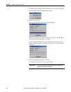
Refer to connector pinout tables in Chapter 3 or the interconnect
diagrams in Appendix A.
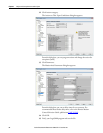
4. Tighten the connector screws.
5. Gently pull on each wire to make sure it does not come out of its terminal;
reinsert and tighten any loose wires.
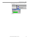
6. Insert the connector plug into the module connector.
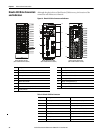
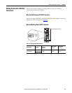
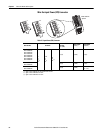
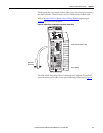
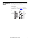
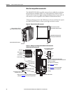
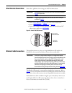
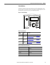
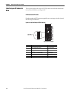
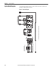
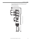
For connector locations of the Kinetix 350 drives, refer to Kinetix 350 Drive
Connectors and Indicators on page 36.
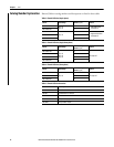
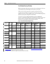
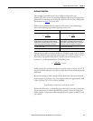
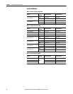
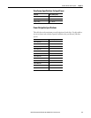
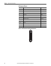
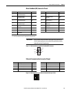
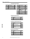
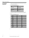
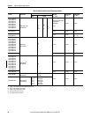
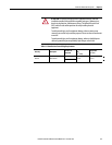
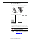
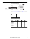
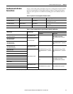
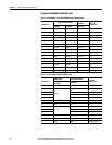
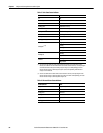
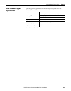
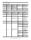
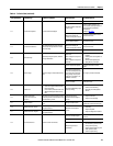
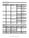
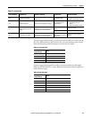
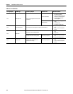
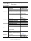
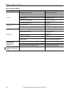
When tightening screws to secure the wires, refer to the tables beginning on
page 59 for torque values.
When removing insulation from wires, refer to the tables beginning on
page 59 for strip lengths.
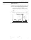
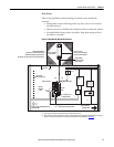
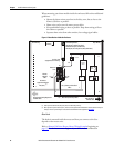
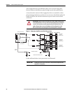
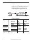
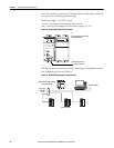
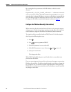
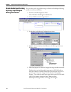
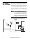
To improve system performance, run wires and cables in the wireways as
established in
Establishing Noise Zones on page 28.
Use caution not to nick, cut, or otherwise damage strands as you
remove the insulation.