Rockwell Automation Publication 2097-UM002C-EN-P - December 2013 51
Chapter 4
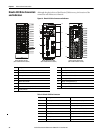
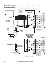
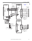
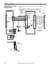
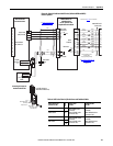
Connect the Kinetix 350 Drive System
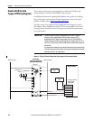
Basic Wiring Requirements
This section contains basic wiring information for the Kinetix 350 drive.
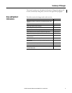
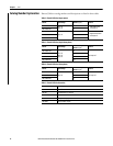
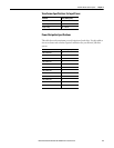
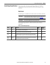
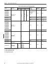
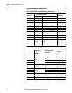
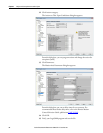
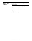
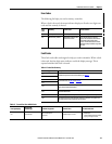
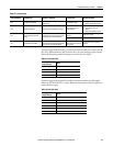
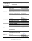
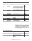
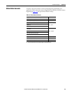
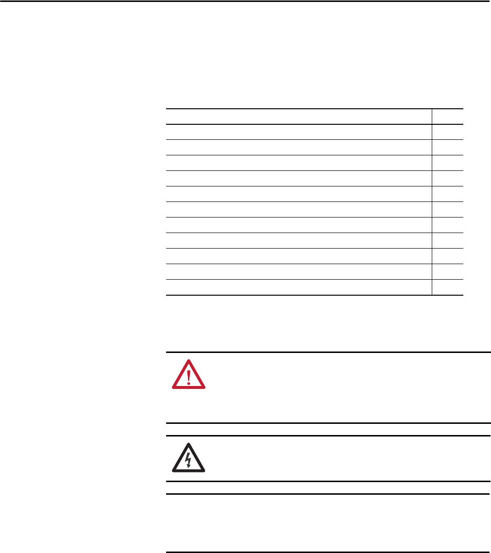
Topic Page
Basic Wiring Requirements 51
Grounding Your Kinetix 350 Drive System 58
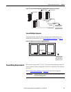
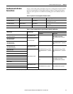
Power Wiring Requirements 59
Wiring Guidelines 62
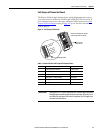
Wiring the Kinetix 350 Drive Connectors 63
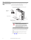
Apply the Motor Cable Shield Clamp 70
Feedback and I/O Cable Connections 71
Wiring the Feedback and I/O Connectors 73
Kinetix 350 Drive (IOD connector and terminal block) 73
Shunt Resistor Connections 75
Ethernet Cable Connections 75
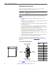
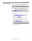
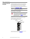
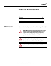
ATTENTION: Plan the installation of your system so that you can perform all
cutting, drilling, tapping, and welding with the system removed from the
enclosure. Because the system is of the open type construction, be careful to
keep any metal debris from falling into it. Metal debris or other foreign matter
can become lodged in the circuitry, which can result in damage to components.
SHOCK HAZARD: To avoid hazard of electrical shock, perform all mounting and
wiring of the Bulletin 2097 drive prior to applying power. Once power is applied,
connector terminals can have voltage present even when not in use.
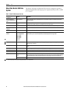
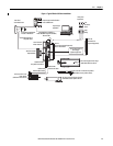
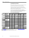
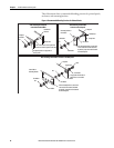
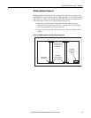
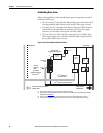
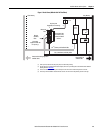
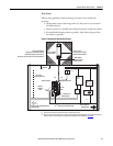
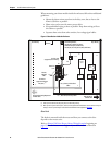
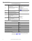
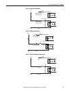
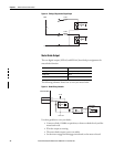
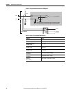
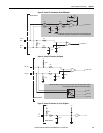
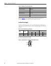
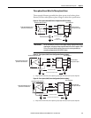
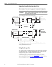
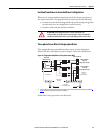
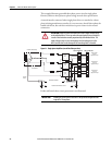
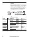
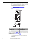
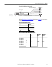
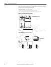
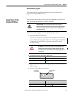
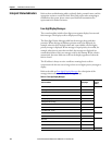
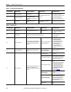
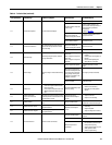
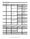
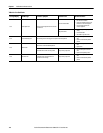
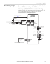
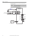
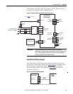
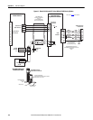
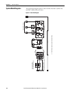
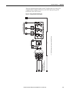
This section contains common PWM servo system wiring configurations, size,
and practices that can be used in a majority of applications. National Electrical
Code, local electrical codes, special operating temperatures, duty cycles, or
system configurations take precedence over the values and methods provided.