


6-15
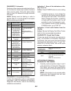
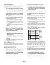
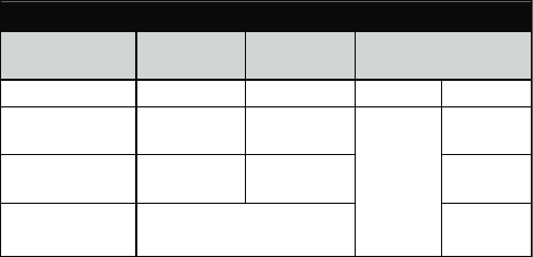
4. Check the lid lock motor winding and
switches by removing P12 from the ma
-
chine/motor control and checking the
resistance values shown in the Lid Lock
Resistance table below:
LID LOCK RESISTANCE
Component
Resistance
Unlocked
Resistance
Locked
Contacts Measured
Motor Winding
35 ±5 Ω 35 ±5 Ω
P12-2 P12-3
Lock Switch -
Home
0 Ω
Open Circuit
P12-1
P12-4
Lock Switch -
Lock
Open Circuit 0 Ω P12-7
Lock Switch -
Lid
Lid Closed = 0Ω
Lid Open = Open Circuit
P12-5
If resistance values are good, go to
step 5.
If switch measurements do not match
the values shown in the table for un-
locked (or locked) conditions, a prob
-
lem exists in the door lid lock. Replace
the door lid lock.
5. If the Manual: Door Lid Switch or Manual:
Door Lid Lock in step 1 failed, then the
machine/motor control has failed:
Unplug washer or disconnect power.
Replace Door Lid Lock assembly.
Perform the Manual: Door Lid Switch
and Manual: Door Lid Lock in step 1 to
verify repair.
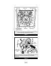
ACCESSING & REMOVING THE
ELECTRONIC ASSEMBLIES
There are two electronic assemblies; the ma-
chine/motor control assembly and the user
interface assembly. See Figures 3 and 4 on
page 6-16.
Accessing the Electronic Assemblies
1. Unplug washer or disconnect power.
2. Remove three screws from the rear of the
console assembly. Pull console towards
front of washer to hinge open and/or re
-
move console.
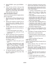
Removing the Machine/Motor
Control Assembly
3. Remove all the wire connections to
the machine/motor control.
•
•
•
•
•
4. Remove the one screw holding the
machine/motor control assembly to
the console tray.
5. There are two plastic legs on the rear
of the machine/motor control assem
-
bly that fit into the console tray. Lift the
front of the control assembly to pivot it
out from the console tray.
Removing the User Interface Assembly
3. Remove the wire connection to the
user interface assembly.
4. Remove the wash cycle selector knob
by firmly pulling on it.
5. The user interface assembly is held
to the console insert panel by three
screws and two locking tabs. After the
screws are removed, lift each of the
locking tabs to remove the back cover
of the user interface assembly.
6. Remove the wash cycle selector
switch from the user interface assem
-
bly opening by lifting the locking tab
on the wash cycle selector switch and
turning the selector switch in a coun
-
terclockwise direction.
7. Three locking tabs located at the bot-
tom of the console insert panel se
-
cure the user interface assembly to
the console insert panel. Using a flat-
blade screwdriver, gently apply pres
-
sure to the locking tabs to release the
user interface assembly.
Reinstalling the Electronic Assemblies
1. Refer to preceding removal sections and
replace in reverse order.
2. Plug in washer or reconnect power.
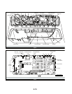
NOTE: When reconnecting wire connections,
route wires as shown in Figure 3, page 6-16.
Be sure to route wires beneath the retainer
clips on the machine/motor control, and en
-
sure user interface assembly wire does not
get pinched between the console assembly
and the console tray when reassembling top.
NOTE: Ensure the console gasket is in place
when reinstalling the console.