


5-3
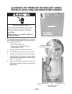
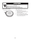
Refer to page 4-6 for the procedure for ac-
cessing the lid lock.
1. Perform the Manual: Door Lid Switch and
Manual: Door Lid Lock tests on page 6-7.
2. Remove the console to access the ma
-
chine/motor control assembly (see “Ac
-
cessing & Removing the Electronic As
-
semblies” on page 6-15).
3. Visually check that the P12 connector is
inserted all the way into the machine/mo
-
tor control.
If visual check passes, go to step 4.
If visual check fails, reconnect P4 and
repeat step 1.
4. Unplug washer or disconnect power.
•
•
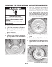
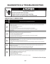
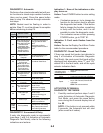
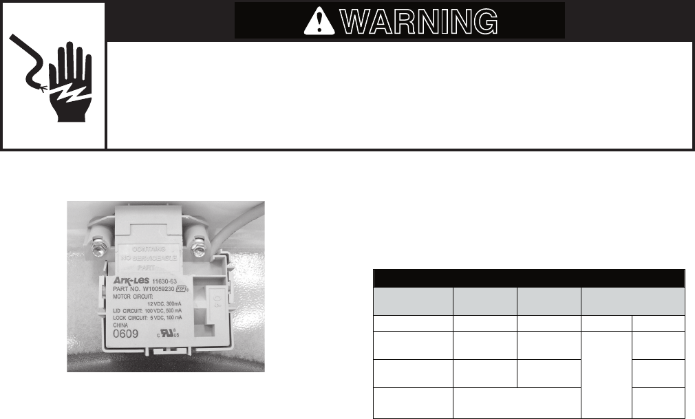
LID LOCK RESISTANCE
Component
Resistance
Unlocked
Resistance
Locked
Contacts Measured
Motor Winding 35 ±5 Ω 35 ±5 Ω P12-2 P12-3
Lock Switch -
Home
0 Ω
Open Circuit
P12-1
P12-4
Lock Switch -
Lock
Open Circuit 0 Ω P12-7
Lock Switch -
Lid
Lid Closed = 0 Ω
Lid Open = Open Circuit
P12-5
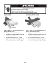
5. Check the lid lock motor winding and
switches by removing P12 from the ma
-
chine/motor control, and checking the
resistance values shown in the following
Lid Lock Resistance table.
If resistance values are good, go to
step 6.
If switch measurements do not match
the values shown in the table for un-
locked (or locked) conditions, a prob
-
lem exists in the door lid lock. Replace
the door lid lock.
6. If the Manual: Door Lid Switch or Manual:
Door Lid Lock tests in step 1 failed, then
the machine/motor control has failed:
Replace machine/motor control as-
sembly.
Perform the Manual: Door Lid Switch
and Manual: Door Lid Lock tests in
step 1 to verify repair.
•
•
•
•
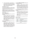
Electrical Shock Hazard
Disconnect power before servicing.
Replace all parts and panels before operating.
Failure to do so can result in death or electrical shock.
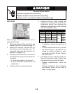
WARNING
LID LOCK