


5-1
COMPONENT TESTING
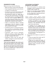
Before testing any of the components, perform
the following checks:
The most common cause for control failure
is corrosion on connectors. Therefore, dis
-
connecting and reconnecting wires will be
necessary throughout test procedures.
All tests/checks should be made with a
VOM or DVM having a sensitivity of 20,000
ohms-per-volt DC, or greater.
•
•
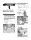
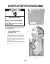
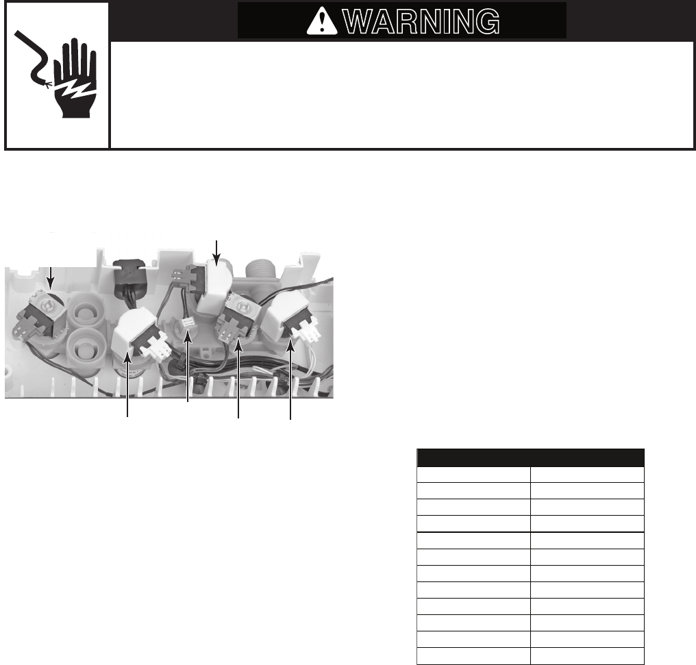
WATER INLET/ DISPENSER
VALVE ASSEMBLY
Check all connections before replacing
components, looking for broken or loose
wires, failed terminals, or wires not pressed
into connectors far enough.
Resistance checks must be made with
power cord unplugged from outlet, and
with wiring harness or connectors discon
-
nected.
•
•
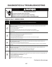
Electrical Shock Hazard
Disconnect power before servicing.
Replace all parts and panels before operating.
Failure to do so can result in death or electrical shock.
WARNING
2. Disconnect the wire connector from the
component under test.
3. Set the ohmmeter to the R x 1 scale.
4. Water Inlet / Dispenser Solenoids: Touch
the ohmmeter test leads to each of the
water inlet/dispenser valve solenoid termi
-
nals. The meter should indicate between
700 and 900
Ω. If the reading is outside
this range, replace the valve assembly.
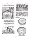
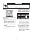
5. Thermistor: Touch the ohmmeter test
leads to the thermistor terminals. The
meter should indicate as shown in the
following chart.
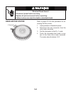
Thermistor
Detergent
Dispenser
Bleach Dispenser
Hot & Cold
Water Inlet Valves
THERMISTOR RESISTANCE
Temperature Resistance
(
40°F (4.4°C) 26–27.5 k Ω
Ω
50°F (10°C) 19–20.5 k
Ω
60°F (16°C) 15–15.7 k
Ω
70°F (21°C) 11.7–12.2 k
Ω
80°F (27°C) 9.1–9.5 k
Ω
90°F (32°C) 7.2–7.6 k
Ω
100°F (38°C) 5.6–5.9 k
Ω
110°F (44°C) 4.6–4.9 k
Ω
120°F (49°C) 3.6–3.8 k
Ω
130°F (55°C) 2.9–3.1 k
Ω
140°F (60°C) 2.4–2.6 k
Ω
)
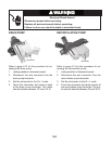
Refer to page 4-4 for the procedure for ac-
cessing the water inlet/dispenser valve as
-
sembly.
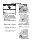
1. Unplug washer or disconnect power.
Fresh Fill
Inlet Valve