


6-10
TEST #2 Log Valve
This test checks the electrical connections to
the valves, and the valves themselves.
1. Check the relays and electrical connec-
tions to the valves by performing the steps
under Diagnostic: Manual, then Manual:
Water Valves. Each step in the test ac
-
tivates a group of valves. The following
steps assumes one (or more) valve(s)
failed to turn on.
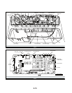
2. For the valve(s) in question check the in-
dividual solenoid valves:
Unplug washer or disconnect power.
Disconnect connector P1 and P2 from
the machine/motor control.See Figure
4, page 6-16.
Check harness connection to solenoid
valves.
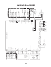
3. Check resistance of valve coils at con-
tacts P1 and P2 shown in the Wiring Dia
-
gram on page 7-1. Resistance values
should match those shown.
If resistance readings are tens of ohms
outside of range, replace the entire log
valve assembly.
If resistance readings are within range,
replace the machine/motor control as
-
sembly.
4. Reconnect connectors P1 and P2 to the
machine/motor control.
TEST #3 Motor Circuit
This test checks the wiring to the motor and
rotor position sensor; and the motor and rotor
position sensor themselves.
NOTE: Drain water from tub.
1. See Activation of Manual Diagnostic Test
Mode, and check the motor and electrical
connections by performing the Spin test
under Manual: Motor. The following steps
assumes that this step failed.
2. Unplug washer or disconnect power.
•
•
•
•
•
3. Check to see if basket will turn freely.
If basket turns freely, go to step 4.
If basket does not turn freely, deter
-
mine what is causing the mechanical
friction or lock up.
4. Remove the console to access the ma
-
chine/motor control assembly. See Ac
-
cessing & Removing the Electronic As
-
semblies.
5. Visually check that the P5 and P10 con-
nectors are inserted all the way into the
machine/motor control.
If visual checks pass, go to step 6.
If visual checks fail, reconnect P5 and
P10 and repeat step 1.
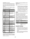
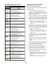
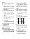
6. Visually check that the P5 and P10 con-
nectors are inserted all the way into the
machine/motor control.
With an ohmmeter, verify resistance
values as shown below:
•
•
•
•
•
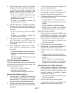
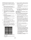
7. Tilt machine forward to access the bottom
of the machine and the drive motor area.
See Figure 1 on page 6-13. Remove the
motor bolt, then the motor cover to ac
-
cess the motor connections. See Figure
2 on page 6-13.
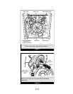
8. Visually check the mounting bracket and
electrical connections to the motor and
rotor position sensor board.
If visual check passes, go to step 9.
If visual check fails, reconnect the elec
-
trical connections, reassemble stator
and motor cover and repeat step 1.
•
•
Check
betwee
n
connector
pins
Resistance values
should be:
Go to
step 7 i
f
values are:
Go to
step 12 if
:
P5
1-5
31 Ω ± 5 Ω
Much higher
than 31Ω
Resistances
at all
connectors
are correct
1-3
P10
6-5
15 k
Ω ± 100 Ω
Much higher
or muc
h
lower than
15 k
Ω
6-4
6-3
1-7
600 Ω t
o
21.2 k
Ω
Out of range