4-16
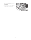
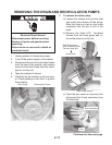
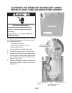
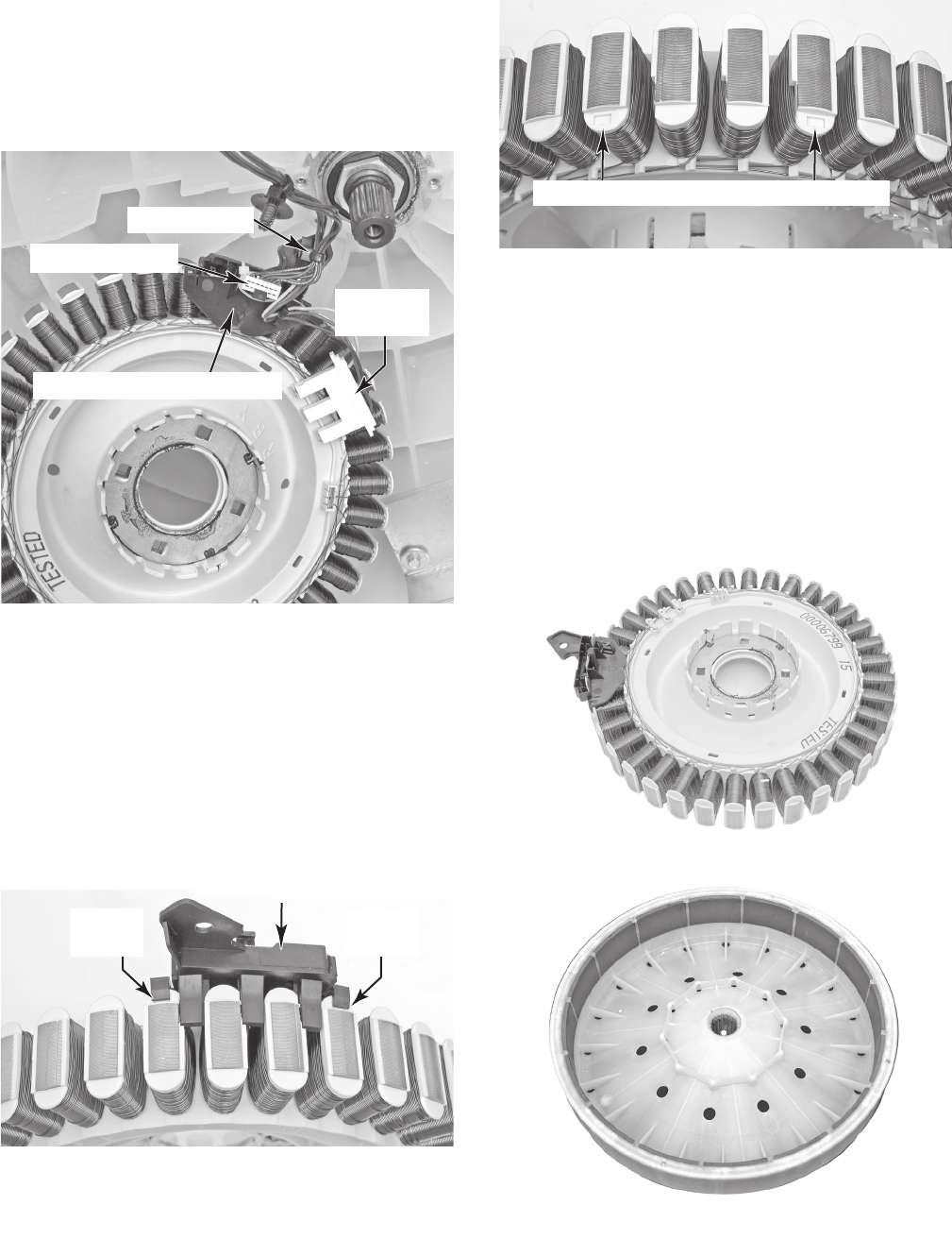
10. Disconnect the power connector from the
stator terminals.
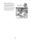
11. Disconnect the wire standoff and edge
connector from the rotor position sensor
cover.
Power
Connector
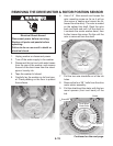
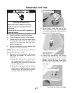
12. Pry up on the two locking tabs and pull
the rotor position sensor cover off the
stator housing.
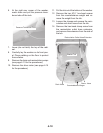
NOTE: In the top right
photo, there are two indents on the hous
-
ing to mark where the rotor position sen
-
sor cover is installed. Be sure to snap the
two tabs on the rotor position sensor cov
-
er into these indents when you reinstall it
on the stator assembly.
Pry Up
Tab
Rotor Position Sensor Cover Tab Indents
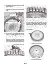
REASSEMBLY NOTE: When you reinstall
the drive motor rotor over the stator assembly,
do not grip the rotor housing around the rear
edge with your fingers. The magnets around
the rotor housing are very strong, and they
will pull the rotor into the stator coil magnets
when the rotor magnets come within their
magnetic field. Keep your fingers along the
outside of the rotor housing and away from
the rear edge when you are installing it on the
stator assembly.
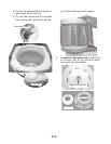
Drive Motor Stator Assembly
Drive Motor Rotor Assembly
Pry Up
Tab
Rotor Position Sensor Cover
Edge Connector
Wire Standoff
Rotor Position Sensor Cover


