


93
• If the power supply responds to the disconnection, there is a problem with the driven load and not
the power supply itself.
• Check ALL loads and retest.
Check that the device’s output voltage is 24 volts DC.
• If not, adjust it.
3. DEFECTIVE ANALOG INPUT MODULE or CHANNEL
Replace Analog Input Module
4. RTD (Resistive Temperature Device) WIRING TO THE “EXHAUST” 4 to 20 MILLIAMPERE
(4 to 20 mA) TRANSMITTER
Check ALL wiring and connection from the exhaust RTD (Resistive Temperature Device) probe to the
exhaust 4 to 20 milliampere (4 to 20 mA) transmitter. Refer to the EXHAUST Temperature Assembly and
Wiring Diagram, Main Panel Wiring Diagram.
5. CIRCUIT WIRING TO THE ANALOG INPUT MODULE
Check ALL wiring and connections from the 4 to 20 milliampere (4 to 20 mA) transmitter to the PLC
(Programmable Logic Controller) Analog Input Module. Refer to the Main Panel Wiring Diagram.
G. MOTORS
Introduction
The four (4) motors installed on the dryer are connected directly to associated thermal magnetic starters in the
main electrical enclosure. The troubleshooting information includes in this section will cover the actuation, power
control and safety devices to these motors.
The motors include:
• MAIN BLOWER FAN MOTOR
• BURNER FAN MOTOR
• LEFT (Basket) TUMBLER MOTOR
• RIGHT (Basket) TUMBLER MOTOR
Refer to the following diagrams for functional, and wiring information:
• ML-460 MAIN PANEL WIRING DIAGRAM
• ML-460 SYSTEM BLOCK DIAGRAM
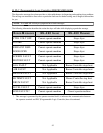
• Motor Actuating Device Information
ALL motor contactors have 120 volts 50/60 Hz actuation coils. Three (3) motor contactors are
actuated by outputs from the PLC (Programmable Logic Controller), and one contactor is actuated by the
Burner Controller Module (BCM).