


61
B. BURNER IGNITION
Introduction
The heart of the dryer’s burner control section is a burner controller module. It is located on the upper right hand
side of the Main Electrical Enclosure panel and is described in detail in Section VI, Part D, Gas Burner and
Ignition System on page 37 through page 45).
As noted below the burner ignition section of the dryer comprises a number of safety devices that have to be
satisfied prior to burner ignition. Messages have been provided to aid one in isolating a specific area, however
knowledge of the system is required to troubleshoot it.
The following information will provide means to respond to “Burner Fault Messages” and to verify ALL the
signals necessary for BURNER IGNITION.
Burner Controller Input Signal Components
• AC POWER TO THE BURNER CONTROLLER
• PLC (Programmable Logic Controller) OUT 4 “HEAT ON”
• FUSE 15
• BURNER DOOR SWITCHES DSA4-A and DSA-B
• LOAD DOOR SWITCH DS1B
• UNLOAD DOOR SWITCH DS2-B
• BURNER FAN AIR PRESSURE SWITCH PRS2
• GAS HI PRESSURE and GAS LO PRESSURE SWITCHES PRS1 & PRS2
• LINT CHAMBER AIR PRESSURE SWITCH
• SIX (6) CHANNEL HIGH TEMPERATURE LIMIT SWITCH
• STOP MOTION DETECTOR RELAY CONTACT SMD NO
• FLAME DETECTOR PROBE
• BURNER CHASSIS GROUND
1. Burner Section Input Circuit Component Description
NOTE: Refer to MLG-460 Ladder Diagram for reference.
• AC POWER TO THE BURNER CONTROLLER
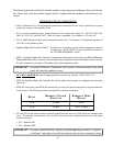
110 VAC power is supplied to the burner controller module PIN #1 through “FUSE 6.” Power is applied
to this point when “MCR” (motor control relay) is closed.
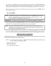
• PLC (Programmable Logic Controller) OUT “HEAT ON”
When this 110 VAC signal is asserted, a number of safety interlocks must be satisfied, before any burner
ignition can take place. This signal is derived from the PLC OUTPUT #4 and is fused.
• FUSE 15
This fuse is located on the upper left hand section of the Main Electrical Enclosure Panel, with the other
PLC output fuses. Its function is to protect PLC (Programmable Logic Controller) output.