


42
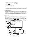
d) Combustion Air Damper
To produce the required combustion airflow, this damper can be adjusted. Remove the screen to
get access to the damper. Moving the damper closer to the blower inlet opening will reduce the
combustion airflow, and moving it away from the blower inlet opening will increase the airflow.
To measure the combustion airflow, attached a manometer to the air pressure tap on the burner
box. The air pressure
should measure 1.25 to 1.50 inches water column (W.C.) (3.1 to 3.73
mbar)
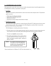
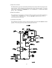
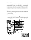
5) Pilot Gas Supply Line
a) The pilot gas supply line consists of a manual shut-off valve, pressure regulator, electric solenoid
valve, back-loaded pressure regulator, and an adjustable gas cock.
b) The gas pressure in this line should be approximately 3.5-inches water column (W.C.) - 8.70
mbar - for natural gas and 1.5-inches water column (W.C.) (3.73 mbar) for L.P. (liquid propane)
gas. This will provide a bushy pilot flame, which produces a signal through the flame rod that is
converted to a 3 DC to 11 volts DC in the burner controller module (BMC).
(1) This flame can be adjusted in two (2) ways.
(a) Pilot Inlet Pressure Regulator
Remove the cap and turn the slotted adjustment screw clockwise (CW) for more gas and
counterclockwise (CCW) for less gas.
(b) Adjustable Pilot Gas Cock
Remove the cap and turn the slotted adjustment screw clockwise (WC) for less gas and
counterclockwise (CCW) for more gas.
(2) The pilot line contains a back-loaded pressure regulator with an impulse line connected to the
gas burner inlet. The regulator will maintain a constant pilot supply pressure in the burner due
to an increase in temperature. DO NOT adjust this regulator.
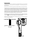
6) Main Gas Supply Line
The main gas supply line consists of a pressure regulator, two (2) motorized shut-off valves, Hi/Lo gas
pressure switch, and manual shut-off valve.
The gas pressure at the burner should be 2.5-inches water column (W.C.) - 6.22 mbar - for natural
gas and 1.25 inches water column (W.C.) - 3.1 mbar - for L.P. (liquid propane) gas. This pressure is
measured by a manometer at the pressure tap which is located above the top manual shut off valve.
a) Motorized Gas Valve
The two (2) 2-inch F.P.T. motorized valve are “ON/OFF” gas flow control valves. The valves
motors operate on 120 VAC and are electrically “cascaded” so that upper valve will not open until
lower valve has fully opened. A limit switch inside the lower motorized valve provides the signal
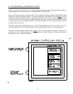
that the valve is fully opened. These valves will open only when the burner controller module
(BCM) is receiving a signal from the flame rod proving that the pilot flame is established.