


36
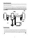
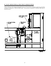
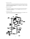
4. Internal and External Pilot Air Supply
On two-way tilt dryers, a pneumatic safety circuit is incorporated to prevent both front and rear tilting pistons
from extending their rods at the same time. When 120 volts is supplied to the “S5” side of the front tilting
piston solenoid valve coil, the round internal spool in the core of the solenoid will move, allowing 80 PSI (5.51
bar) air to flow into the bottom ports of the front tilting pistons, while the top ports of these pistons are bled to
the atmosphere. In addition to this 120 volt electrical signal, the spool also requires a 30 PSI (2.06 bar) supply
(551.6 kPa) air supply connected to port no.1 through holes in the body of the solenoid valve or it can be
supplied externally through the 1/8-inch F.P.T. connection located on either end of the solenoid valve. If no
pilot air is supplied to the solenoid valve. Then the spool cannot move, even with voltage supplied to the
solenoid valve coil.
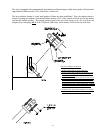
This can be used to prevent both sets of tilting pistons from extending their rods at the same time. When the
front tilting piston rods are extended, 80 PSI (551.6 kPa) air is connected to the bottom piston ports, while the
top piston ports are bled to the atmosphere. So, by tapping the external pilot air supply to the rear tilting rods
are extended, then there is no pilot pressure available to the rear tilting piston solenoid valve so that its spool
cannot move and the rear tilting piston rods cannot extend if a 120 volt signal is sent to its “12” side solenoid
valve coil.
The external pilot air supply to the front tilting piston is tapped off the rear tilting piston top port air line so that
whenever the rear piston rods are extended, there is no pilot air supplied to the front tilting piston solenoid
valve and the front tilting piston rods cannot extend. On the solenoid valve supplied on the dryer, the “12” side
valve is externally piloted, while “14” side valve is internally piloted.
A valve can easily be checked for internal or external piloting by removing the two (2) screws which hold the
solenoid operator onto the valve. For an internal pilot air to be supplied to the valve spool. For an external
pilot, the solid sealing disc must be positioned on top of the internal port.
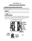
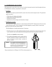
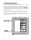
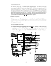
5. Loading Doors and Heat Reclaimer, Cool Down and Intake Air Damper
These solenoid valves are located in the 6-station manifold block on the pneumatic control panel. Each door
piston is controlled by two (2) 2-port/2-position solenoid valve. The heat reclaimer is controlled by one (1)
2-port/2-position solenoid valves.
The three (3) pistons that control the heat reclaimer damper, cool down damper, and intake air damper are
controlled by a single 3-way double acting solenoid valve.
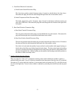
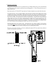
To open the front loading door, a 120 volt signal is applied to “S1,” the coil of the valve that supplies air to the
load door or the heat reclaimer’s bottom port. The valve will open, and 80 PSI (551.6 kPa) of air is supplied
to the bottom port of the piston. The piston rod will extend, and the door will open. No voltage is applied to
“S2,” the coil of the valve that controls the air supply to the door pistons top port so that this line is bled to the
atmosphere.
To close the front loading door or heat reclaimer damper, the voltage signals are reversed, and the loading
door will close.