


45
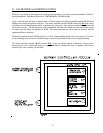
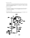
Once the flame probe signal is detected by the burner controller module (BCM), it waits
5-seconds to allow the pilot to stabilize and then opens the main motorized gas valves
(BCM terminal #5) in sequence.
The lower valve opens first. Upon full opening, its’ internal switch closes, enabling the
second motorized valve to open and full flame to be achieved.
If flame failure occurs within a 35-second period, the BCM (burner controller module) will
recycle the ignition sequence once. If flame fails a second time, the system will lock out
and the “FLAME FAILURE” pilot will light.
Once main flame is established, the burner will remain in the full fire mode until the drying
set point temperature has been reached. At this point, the dryer computer will cycle the
top motorized gas valve to the closed the position. The “OFF” mode will be maintained
until the dryer’s temperature falls below the drying set point temperature. The motorized
valve will then be returned to the full fire position. With voltage applied to the motorized
valve, it moves to the full fire position. “OFF” is achieved when no voltage is applied to the
motorized valve.
7) Gas Burner Start-Up
a) New gas lines are filled with air and must be purged before the burner will light. To do this close
the upper manual shut-off valve, but leave the pilot line shut-off open. Push in the Test and Reset
Button on the cover of the burner controller module (BCM). This will “freeze” the ignition
sequence when the pilot flame ignites. This allows time to examine the pilot flame, and measure
the flame rod signal to the BCM.
b) Connect a pressure gauge or water tube to the pilot gas pressure tap. Start the dryer;
Follow the ignition process by referring to the “Sequence of Operation” section of this manual.
c) When the pilot flame is ignited, the pilot gas pressure should measure 3.5-inches water column
(W.C.) - 8.70 mbar - for natural gas and 1.5-inches water column (W.C.) - 3.73 mbar - for L.P.
(liquid propane) gas. The pilot flame should be about as big as a tennis ball.
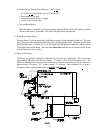
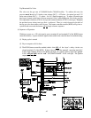
d) Once the pilot has been properly set, remove the pressure gauge from the pilot line connect a
differential pressure gauge between the main gas pressure tap (HI port) and the air pressure tap
(LO port) on the side of the gas burner box. The lines connecting the gauge to these taps must be
long enough to allow the gauge to sit outside of the dryer so that the burner section access door can
be closed when the dryer runs. Running the dryer with these doors open will give an incorrect air
pressure reading.
e) Once this differential gauge is installed, open the main gas shut-off valve and push the Test and
Reset Button on the burner controller module (BCM) so that the button springs out. Restart the
dryer. The ignition process should now continue to the full gas flow state. The differential gauge
should read 2.5 inches water column (W.C.) - 6.22 mbar - for natural gas and 1.25 inches water
column (W.C.) - 3.1 mbar - for L.P. (liquid propane) gas. If it does not, adjust the top motorized
valve as described in the Top Motorized Gas Valve on page 43.