


20
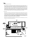
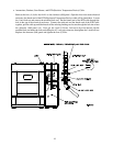
3. Gas Piping
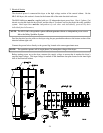
The gas connection to the dryer is made into the 2-1/2” (5.08 cm) F.P.T. shut-off valve located in the bottom
front corner of the lower heat console.
The gas pressure supplied to the dryer must be between 7-inches (17.41 m bar) and 13-inches water
column (W.C.) (32.34 mbar) for natural gas or between 10.5-inches water column (W.C.) -26.12 m bar- for
L.P. (liquid propane) gas.
If the facilities gas pressure is higher than these values, an external pressure regulator must be installed
prior to the dryer to reduce the gas pressure to within the appropriate range.
The dryer must be connected to either natural or L.P. (liquid propane) gas indicated on the dryer data label
located on the inner right wall of the electric cabinet. If your gas supply does not match the type of gas for
which the dryer was built, contact your distributor or the ADC factory.
1. The installation must conform with local codes or, in the absence of these local codes, with the National
Fuel Gas Code, ANSI Z223.1 or the CAN.CGA-B149, Installation Codes.
2. The dryer and it’s individual shutoff valve must be disconnected from the gas supply piping system during
any pressure testing of that system at test pressures in excess of 1/2 psi (3.5 kPa.)
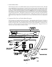
Pipe joint compounds that resist the action of natural and L.P. (liquid propane) gas must be used.
Test ALL pipe connections for leaks by brushing on a soapy water solution.
WARNING: NEVER TEST FOR LEAKS WITH A FLAME!!!
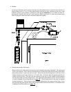
4. Exhaust Air Ducting
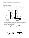
The dryer’s exhaust air must be vented to the outdoors by the shortest route possible with the number of
elbows kept to a minimum. The duct should be designed and installed by qualified technicians.
Improperly designed duct work reduce the airflow through the dryer, causing improper and unsafe drying
conditions. The static pressure of the air in the duct work must not exceed 1.25-inch water column
(3.1 millibar). The dryer exhaust 11,600 cfm (cubic feet per minute) - 328.5 cmm (cubic meters per
minute) - of air during the drying cycle, 13,000 cfm - 368 cmm - during cool down. Ducting must be sized
for the 13,000 cfm 368 cmm of airflow.
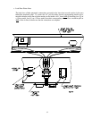
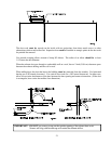
The exhaust vent connection is located on top of the burner and heater section of the dryer. It has rectangle
cross-section and is flanged.
A sheet metal transition piece is supplied to connect a 24-inch (60.96 cm) diameter exhaust duct to the
dryers’ exhaust vent connection. Care must be taken in locating this transition piece so that the tilting
tumbler (basket) does not hit the transition piece.
The duct wire connecting the vent to the outdoors must be a minimum of 24-inches (60.96 cm) in diameter
for a round duct or 625 square inches (4032.25 sq cm) for a rectangular duct (22-inches x 22-inches
square duct [55.88 cm x 55.88 cm] would be sufficient).