


14
2. Electric
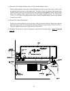
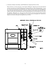
a. Burner Switch and Air Switch
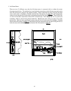
These connections are made between the upper heat module and the lower heat module section. To
connect the burner, there are three (3) wires that come from the ignition transformer through (2) holes on
the bottom of the upper heat module. The green and red wires are fed through the hole closest to the
doors and the high voltage wire gets put through the hole nearest the tumbler. The green wire has a ring
terminal that gets mounted to the burner assembly. The red and high voltage wires need to have the
provided connectors installed on the ends of the wires. Take stripped end of the wire and put it through the
end of the black cap, then, tighten the metal end clip. The red wire goes on the flame probe behind the
pilot line and the high voltage wire goes on the spark plug (spark plug closest to the front).
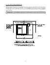
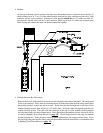
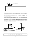
b. Burner Fan
The burner fan connections are made in the back of the burner fan motor. Remove the two (2) screws
that hold the cover to the junction box of the motor. The burner fan cable with the four (4) conductors in
it can be found next to the heat reclaimer piston. Connect the 90° end connector of the cable to the motor
junction box with the lock nut. After the cable is mechanically fastened to the motor begin to connect the
wires with the same color tape identifiers together. CAUTION: There may be more than two (2)
connections at one junction with wire and PVC electrical tape.
The green wire is ground and gets connected to the ground lug in the motor. Replace the two (2) screws
and the cover for the burner motor junction area.