


17
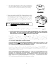
If the dryer repeatedly has DSI module "LOCK-OUT" failures, the cause may be due to high voltage
not getting into the DSI module probe circuit.
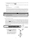
(1) Check to insure that the red high voltage wire (between the ignitor spark electrode and the
DSI module) is not wrapped around the sensor probe wire (the wire between the DSI module
FP terminal and the ignitor and flame-probe assembly). If the wires are touching one another,
separate and secure in place AWAY FROM ONE ANOTHER.
(2) Check to insure that the dryer is properly grounded and that the ground connections (GND) to
the DSI module are secure.
(3) If the problem persists, it is most likely to be in the external components (not the DSI module),
or wiring , due to a "FLAME-OUT" ... proceed as follows:
NOTE: Preliminary steps - DO NOT OMIT - to minimize the time required to troubleshoot this
system.
(a) Disconnect the electrical power to the dryer.
(b) Visually check the DSI module components for visual damage.
(c) Check wiring for loose connections, nicks or cracking at the ceramic insulator, or shorting
of the sensor to the burner.
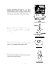
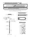
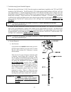
(d) Inspect the DSI ignitor and flame-probe assembly...
...check electrode for visible cracking at the ceramic insulator or shorting of sensor to burner
...check to insure that the flame sensor rod is positioned over the flame area
...check for carbon deposits on the flame sensor rod
...check to insure that there is a 1/8" gap between the ground rod and the ignitor spark
electrode
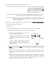
b. After preforming these inspections and making corrections - if any - restore power to the dryer ... start the
dryer and operate through one (1) complete cycle to insure that ALL components are functioning properly.
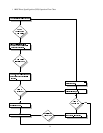
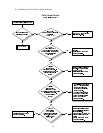
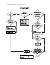
If a no heat condition persists refer to the Troubleshooting Flow Charts on pages 19, 20, and
21.
1) To effectively use this information or the flow charts, each step must be completed in sequence,
performing whatever test are suggested. After the completion of each test, the guide will direct the
Service Technician to the next logical step in the troubleshoot sequence based on the outcome of the
previous check.
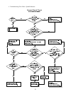
2) Components should be replaced only after each step has been completed and replacements after
each step has been completed and replacement is suggested in the flow chart. However, the experienced
technician realizes that a loose connection or broken or shorted wire may be at fault where electrical
components are concerned... and not necessarily the suspected component itself.