


73
7.
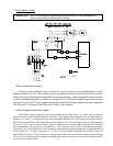
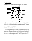
Cycle Done Circuit:
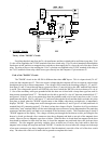
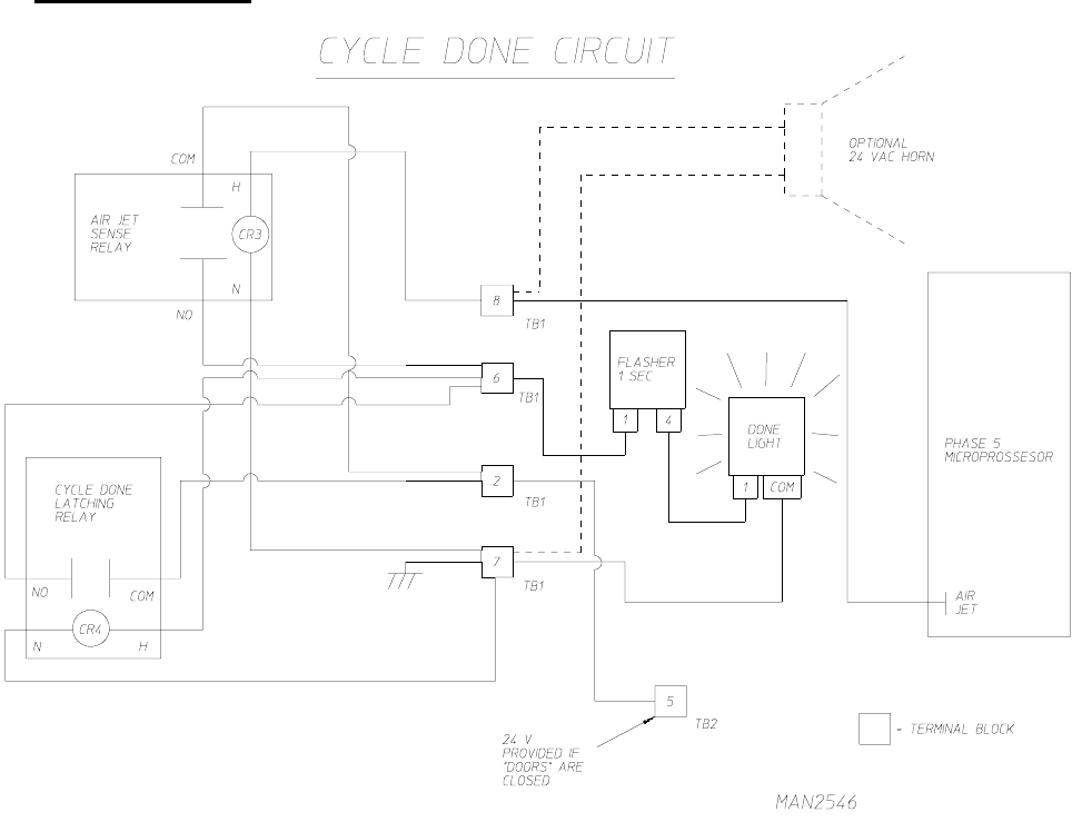
Theory of the "CYCLE DONE" Circuit:
When the dryer has come to the end of the drying/cooling cycle of the dryer the air jet spade terminal on
the microprocessor will be energized with 24 A/C volts. This 24 A/C volts will then be present across the coil of
the air jet sensor relay. The relay closes and the 24 volts from the door circuit passes through the air jet sense
relay, via cycle done latching relay coil. This cycle done latching relay closes passing through the 24 volts from
the door switch circuit to the done light flasher causing the done light to flash.
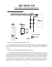
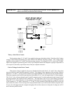
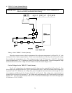
Path of Voltage for the "CYCLE DONE" Circuit:
The 24 A/C volts for this circuit is taken off the air jet terminal on the computer board. The voltage then
travels to TB1 #8 from there it supplies the coil voltage for the air jet sense relay. The COM. terminal of the relay
is connected to TB1 #2, which is supplied with 24 A/C volts when the door switch circuit is complete. Now with
the relay energized the 24 A/C volts applied to the COM. terminal of the relay will be present on the NO. terminal
via, TB1 #6 which now energizes the pin #1 of the 1 sec. flasher. The output of the flasher (PIN #4) will be
connected to the "DONE LIGHT" and with the other terminal of the "DONE LIGHT" grounded via TB1 #7 the
light will flash in 1 second intervals.