


25
3) Air Turbulence
If there is sail switch flutter due to air turbulence or improper impellor (fan and blower) rotation or a
restriction in the exhaust duct work, the DSI module will cycle erratically. This in turn might cause
the DSI module to "LOCK-OUT" (where the L.E.D. indicator will LIGHT "RED" CONTINUOUSLY).
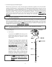
a) If air turbulence cause the flame to move away from the flame probe electrode (of the ignitor and
flame-probe assembly), or if the flame goes out completely during the heat (flame) cycle, the DSI
module will attempt to reestablish a flame by going into a reignition cycle.
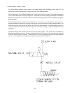
4) Direct Spark Ignition (DSI) Module
If there is some sort of operational interference in the DSI system, the DSI module (acting as the
"controller" for the system) will go into a "LOCK-OUT" mode (where the L.E.D. [light emitting
diode] indicator will LIGHT "RED" CONTINUOUSLY).
a) Operational interference is any adverse condition (whether internal or external) to the system.
(Electrical noise is considered external noise interference because it can cause the DSI module
to cycle erratically.)
NOTE: To reset the DSI module if it is in the "LOCK-OUT" mode, open and close the main
door, then restart the dryer.
If the GAP, the ALIGNMENT, and the POSITION of the ignitor and flame-probe assembly are correct,
if the gas flow and pressure is constant and consistent; if there is no adverse air turbulence; and if the DSI
module remains in the "LOCK-OUT" mode (where the L.E.D. indicator will LIGHT "RED"
CONTINUOUSLY) then, there is a malfunction with the DSI module itself, and it must be replaced.
5) Wiring
If the DSI module is in the "LOCK-OUT" mode (where the L.E.D. indicator will LIGHT "RED"
CONTINUOUSLY) , and the mechanical components have been checked (i.e., the ignitor/flame-
probe assembly, the gas valve, etc.), then, there may be a problem somewhere in the DSI system
wiring.
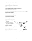
a) Check ALL the wiring within the DSI system, especially the ground connections at the DSI
module and the ignitor and flame-probe assembly.
NOTE: Check for any possible damage to the ceramic insulators on the ignitor electrode and the
flame-probe electrode of the ignitor/flame-probe assembly.
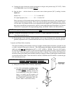
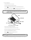
b) Make sure the flame-probe electrode of the ignitor and flame-probe assembly is positioned no more
than one (1) inch maximum from the burner tube.
CAUTION: DO NOT LET THE IGNITOR AND FLAME-PROBE ASSEMBLY TOUCH
THE BURNER TUBES; OTHERWISE THE ENTIRE ASSEMBLY WILL
SHORT OUT.