


66
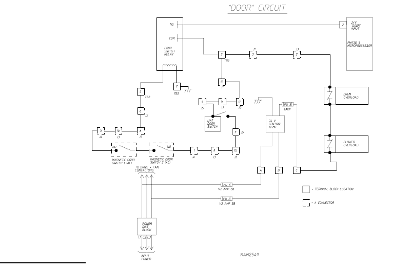
2. "DOOR" Circuit
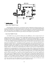
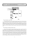
Theory of the "DOOR" Circuit:
Providing that the 4 amp fuse, the 24 volt transformer, and the overloads (drive and blower) are okay, 24 A/
C volts will be supplied to the "COM" terminal of the door switch relay. This 24 volts is branched off through the
lint drawer switch, and the two magnetic door switches to then supply the 24 volts to the coil of the door switch
relay. The relay will now close sending the 24 A/C volts that was supplied to the "COM" terminal of the relay to
the "N/O" terminal of that relay which in turn goes directly into the computer 15 pin connector #2.
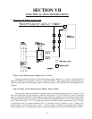
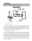
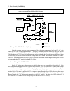
Path of the "DOOR" Circuit:
The "DOOR" circuit in the AD-200 is different than other ADC dryers. This is a input circuit (24 A/C
volts) into the computer pin #2. This is the control voltage that the computer will use to output at various times
throughout the cycle to various components. The voltage will first start at the incoming voltage L1, L2, and L3,
from there L1 and L3 travel through the two protection fuses (.5 amp slo-blo) to the ABC terminal block letters
A and B. The voltage at this point is still 208/240 volts, here is where the 208/240 volts is cut down to 24 volt A/
C. One of the secondary wires gets grounded while the other one is fused with a 4 amp buss type fuse, and it's
then present at terminal block "C". We should now be able to get the 24 volts A/C between terminal block "C"
and ground. If the 24 volts is not present here then the problem could only be bad 4 amp fuse or the 24 volts
transformer has failed. The 24 volts leaves "C" and travels through the blower and the drum overloads, this is the
first place to check when the "DOOR" signal comes on the display when these overloads trip, it immediately
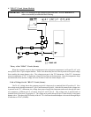
displays "DOOR". The voltage now travels through some connectors (J1 and J3 pin #2 of each) and lands on
terminal block #2, connecting point #2. This here is where the voltage will split. From here it will go to the door
switch relay "com" terminal, and it will also travel through some connectors, see the diagram above for particular
connectors and there pin#'s, and land on one terminal of the lint drawer switch. This is another spot to check if
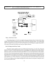
"DOOR" appears on the display. The voltage will then pass through the lint drawer switch, providing the lint
drawer is closed, go through a few connectors (see above diagram) and land on one pin of the magnetic door
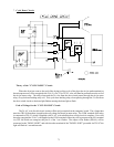
switch. Here we use two magnetic type door switches. When the door is closed there are magnets on the door
that should be adjusted so that when the door is closed the magnets are positioned above the pick-ups (door
switches). The two magnetic proximity switches (door switches) are in series, they both need to sense the
magnets or the voltage will stop here and read "DOOR". From the two door switches the voltage travels through
a few more connectors (see above diagram) and it's final destination is one side of the coil of the door switch
relay. The other side of this coil is hard wired to ground to complete this circuit.