


© Copyright, Alliance Laundry Systems LLC – DO NOT COPY or TRANSMIT
Installation
510975
28
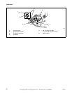
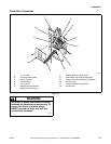
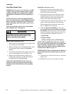
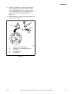
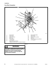
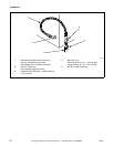
Four-Wire Connection
Figure 17
D683I
1 Ground Wire 8 Neutral (White Wire)
2 White Wires 9 Strain Relief
3 Neutral Terminal 10 Power Cord (Four-Wire)
4 Black Wire 11 Red Wire
5 Terminal Block 12 Terminal Bracket Ground Screw
6 “L2” Terminal 13 “L1” Terminal
7 Slotted Hex Head Screws
(Shipped inside the dryer or removed in step 2)
D683I
1
2
3
4
5
12
11
10
9
8
7
6
4
1
13
11
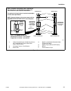
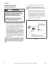
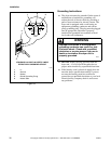
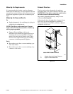
Dryer unit is shown with the access cover
removed for illustration purposes only. To
reduce the risk of an electric shock,
NEVER operate the dryer unit with the
access cover removed.
W150
WARNING