Page 876 of 906 QPC841 Quad Serial Data Interface card
553-3001-211 Standard 3.00 August 2005
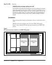
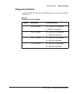
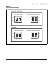
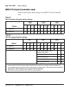
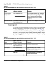
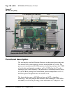
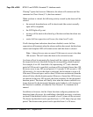
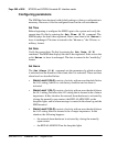
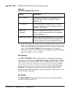
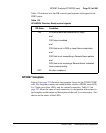
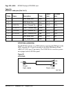
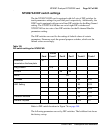
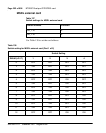
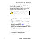
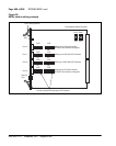
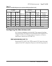
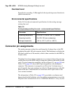
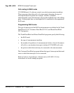
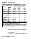
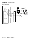
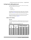
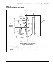
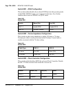
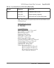
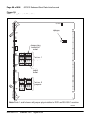
Configuring the QSDI card
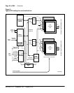
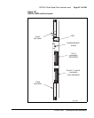
Configuring the QSDI card consists of setting these option switches for each
serial port:
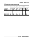
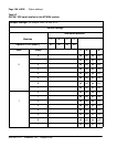
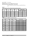
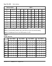
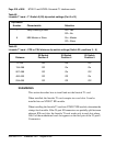
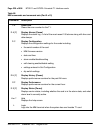
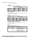
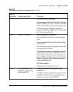
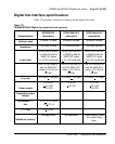
• Port address
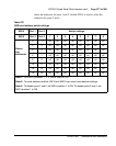
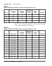
• Baud rate
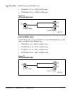
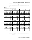
• DTE/DCE mode
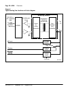
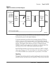
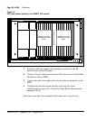
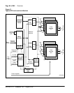
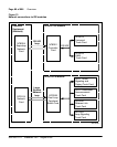
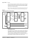
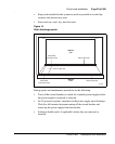
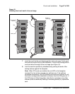
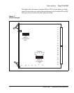
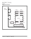
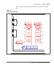
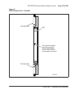
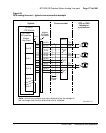
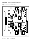
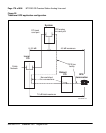
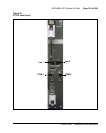
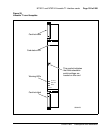
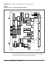
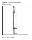
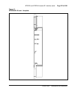
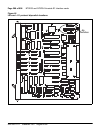
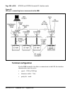
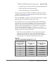
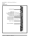
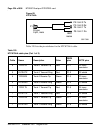
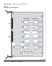
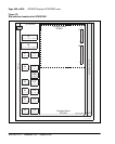
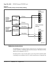
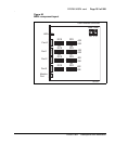
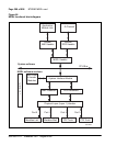
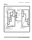
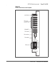
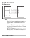
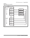
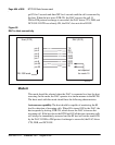
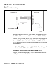
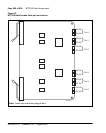
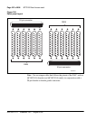
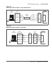
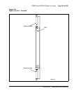
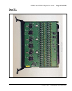
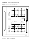
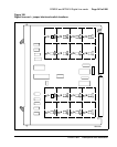
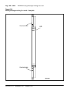
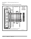
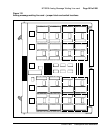
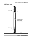
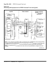
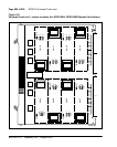
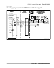
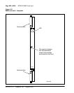
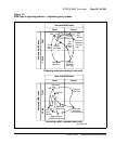
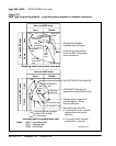
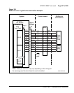
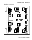
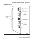
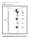
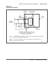
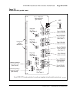
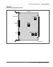
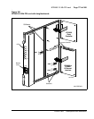
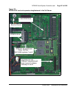
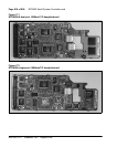
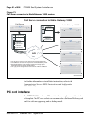
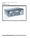
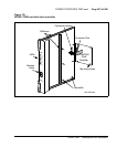
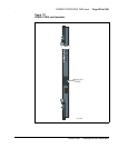
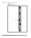
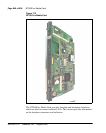
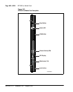
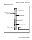
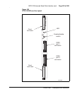
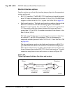
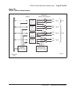
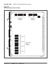
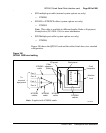
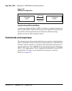
Figure 189 on page 880 shows the location of the option switches on the
QSDI card. Instructions for setting these switches are in the section that
follows.
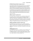
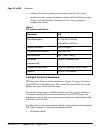
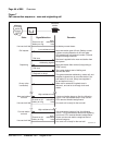
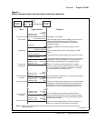
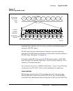
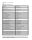
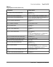
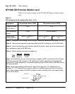
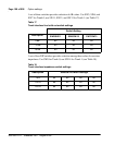
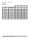
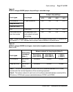
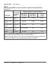
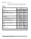
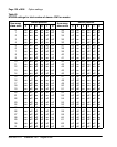
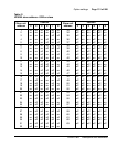
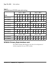
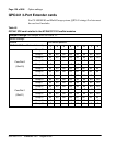
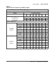
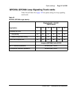
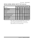
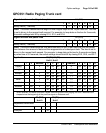
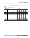
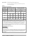
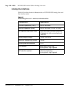
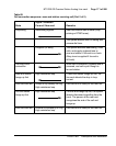
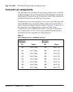
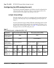
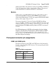
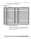
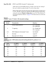
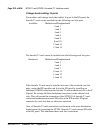
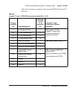
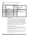
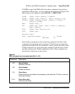
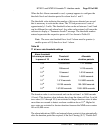
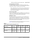
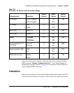
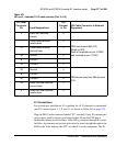
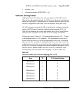
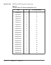
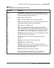
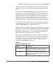
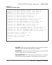
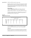
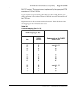
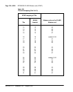
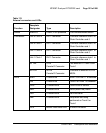
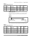
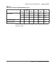
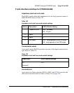
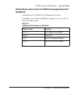
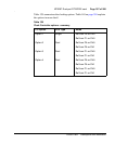
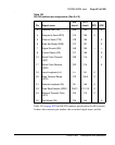
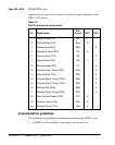
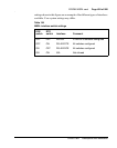
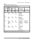
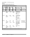
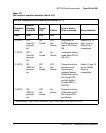
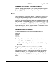
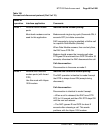
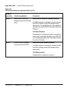
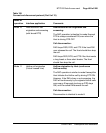
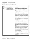
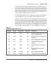
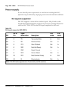
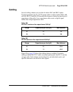
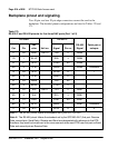
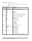
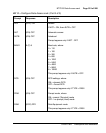
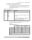
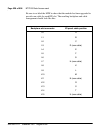
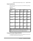
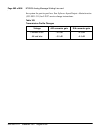
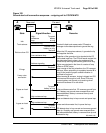
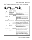
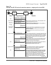
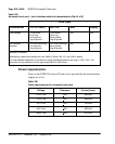
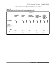
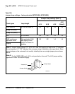
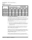
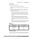
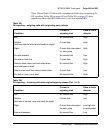
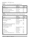
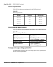
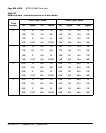
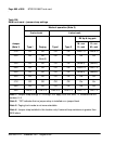
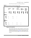
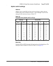
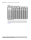
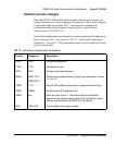
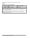
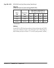
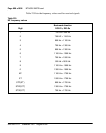
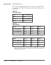
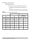
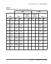
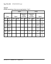
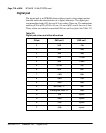
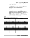
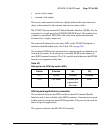
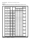
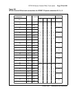
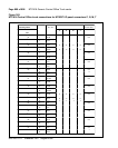
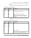
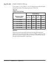
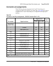
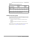
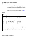
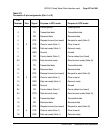
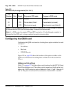
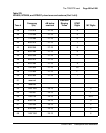
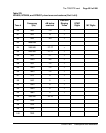
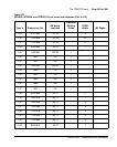
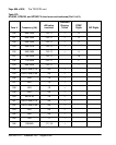
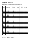
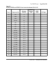
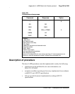
Address switch settings
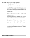
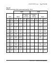
Table 275 on page 877 lists the address switch settings for the QPC841 Quad
Serial Data Interface card. The address select jumpers and logic on the card
address the UARTs using two pairs of addresses: 0 and 1, 2 and 3, through 15
and 16. The pairs do not need to be consecutive. Switch SW14 is used to
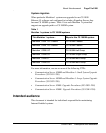
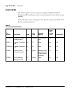
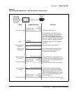
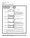
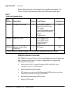
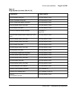
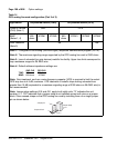
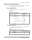
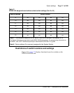
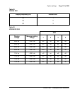
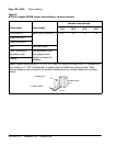
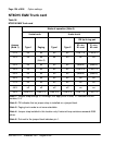
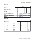
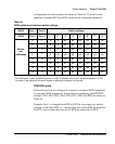
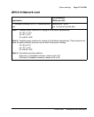
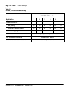
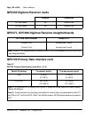
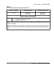
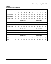
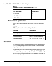
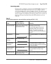
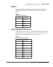
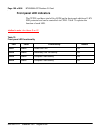
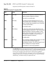
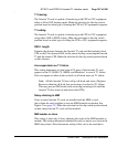
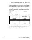
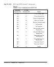
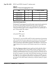
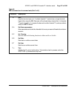
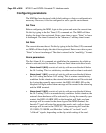
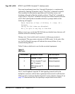
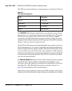
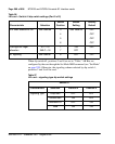
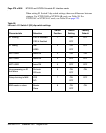
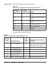
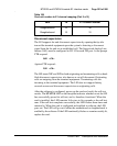
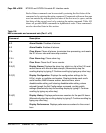
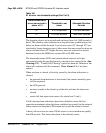
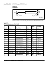
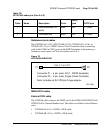
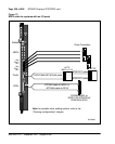
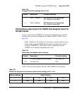
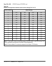
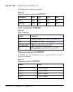
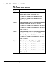
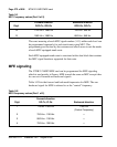
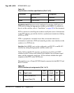
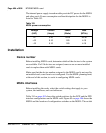
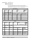
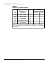
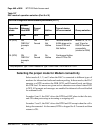
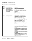
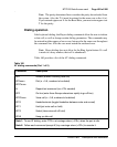
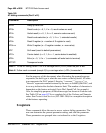
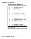
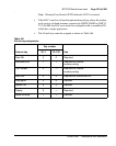
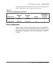
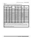
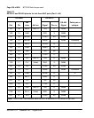
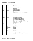
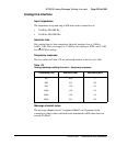
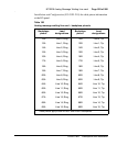
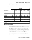
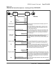
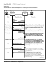
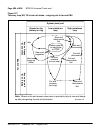
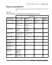
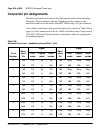
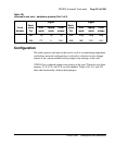
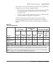
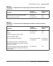
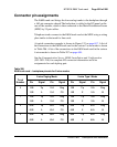
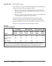
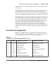
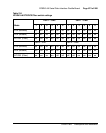
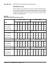
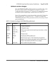
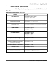
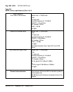
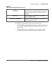
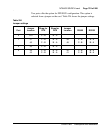
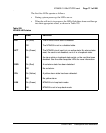
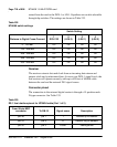
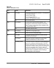
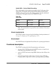
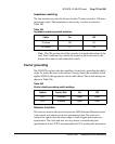
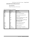
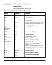
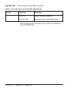
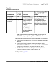
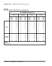
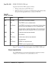
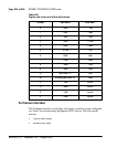
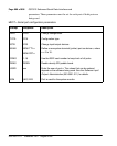
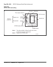
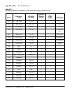
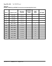
19 GND Ground Ground
21 CD Carrier detect (Note 1 Carrier detect (not used)
22 DTR Data terminal ready Data terminal ready (Note 2))
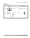
Note 1: In DTE mode, the signals CD, DSR, and CTS are tied to +12 volts (through a resistor)
to indicate that the QSDI port is always ready to transmit and receive data.
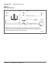
Note 2: In DCE mode, the signals DTR and RTS are tied to +12 volts (through a resistor) to
indicate that the QSDI port is always ready to transmit and receive data.
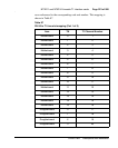
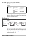
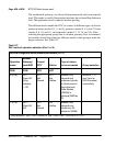
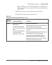
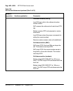
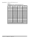
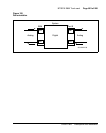
Table 274
Connector J2 pin assignments (Part 2 of 2)
Pin
Number
Port Signal Purpose in DTE mode Purpose in DCE mode