NTAK09 1.5 Mb DTI/PRI card Page 711 of 906
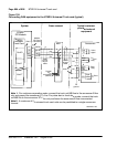
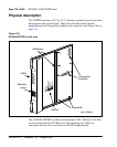
Circuit Card Description and Installation
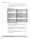
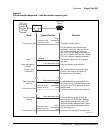
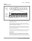
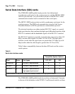
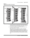
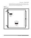
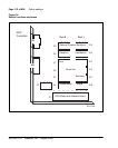
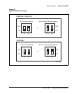
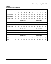
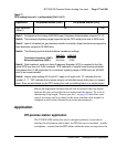
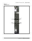
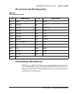
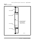
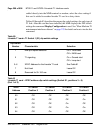
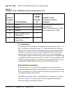
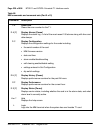
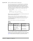
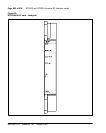
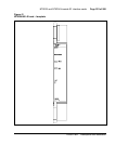
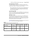
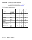
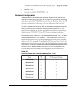
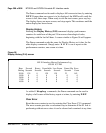
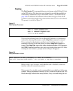
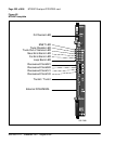
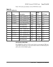
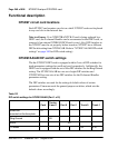
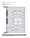
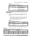
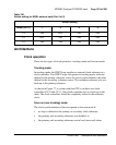
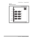
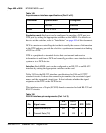
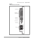
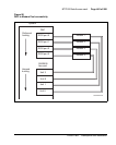
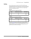
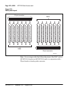
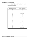
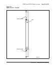
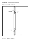
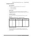
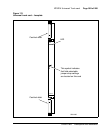
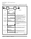
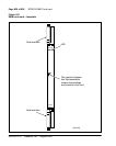
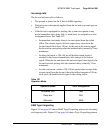
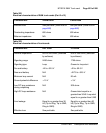
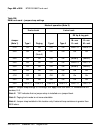
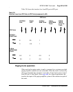
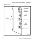
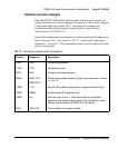
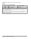
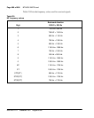
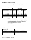
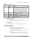
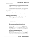
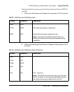
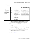
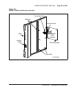
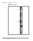
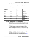
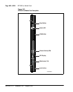
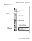
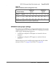
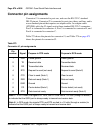
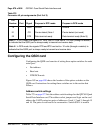
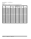
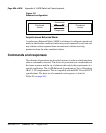
The first five LEDs operate as follows:
• During system power up, the LEDs are on.
• When the self-test is in progress, the LEDs flash three times and then go
into their appropriate states, as shown in Table 229.
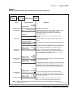
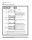
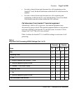
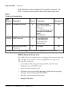
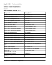
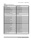
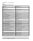
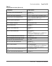
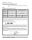
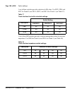
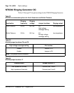
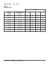
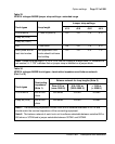
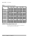
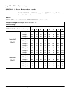
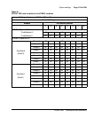
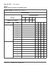
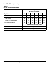
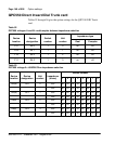
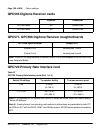
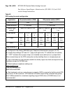
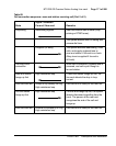
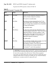
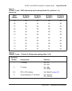
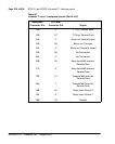
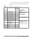
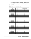
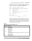
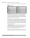
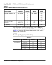
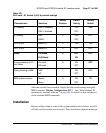
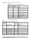
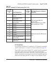
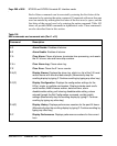
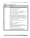
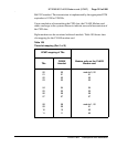
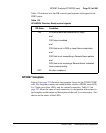
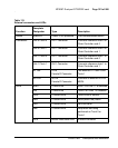
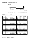
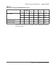
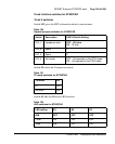
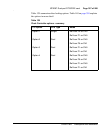
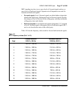
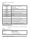
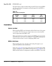
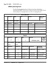
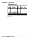
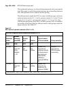
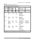
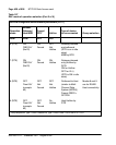
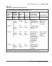
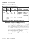
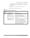
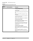
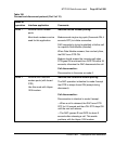
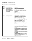
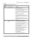
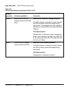
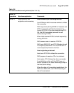
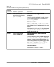
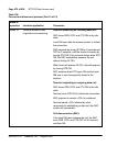
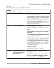
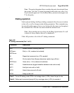
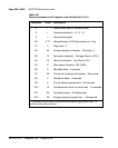
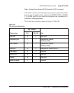
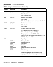
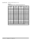
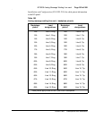
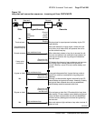
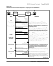
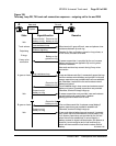
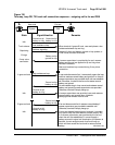
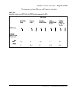
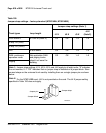
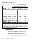
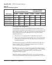
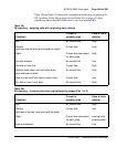
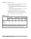
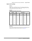
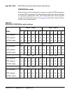
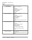
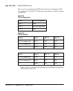
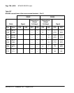
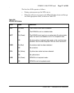
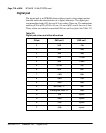
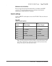
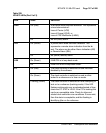
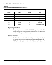
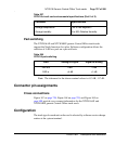
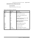
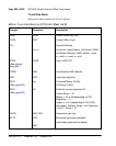
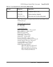
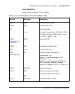
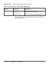
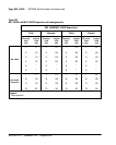
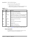
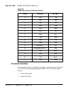
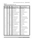
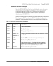
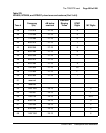
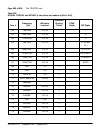
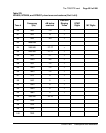
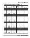
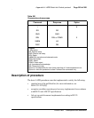
Table 229
NTAK09 LED states
LED State Definition
DIS On (Red) The NTAK09 circuit card is disabled.
Off The NTAK09 is not in a disabled state.
ACT On (Green) The NTAK09 circuit card is in an active state. No alarm states
exist, the card is not disabled, nor is it in a loopback state.
Off An alarm state or loopback state exists, or the card has been
disabled. See the other faceplate LEDs for more information.
RED On (Red) A red-alarm state has been detected.
Off No red alarm.
YEL On (Yellow) A yellow alarm state has been detected.
Off No yellow alarm.
LBK On (Green) NTAK09 is in loop-back mode.
Off NTAK09 is not in loop-back mode.