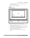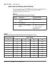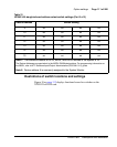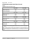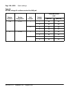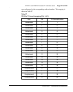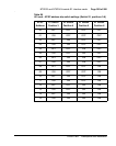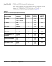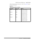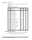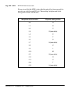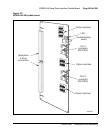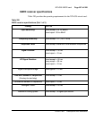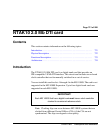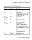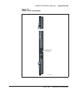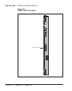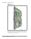
NT6D80 MSDL card Page 411 of 906
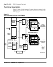
Circuit Card Description and Installation
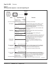
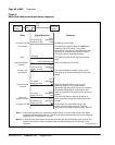
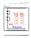
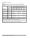
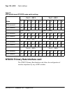
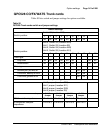
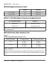
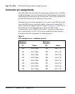
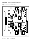
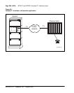
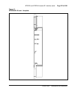
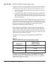
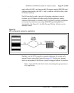
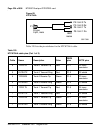
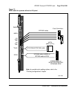
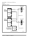
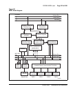
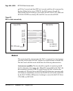
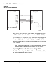
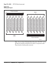
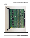
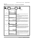
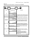
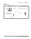
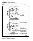
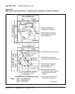
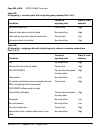
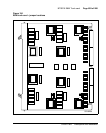
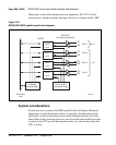
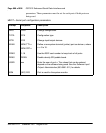
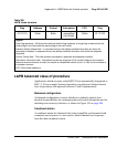
5 Plug the DB15 male connector end of the cable into the J5 DB15 female
connector on the PRI card.
6 Secure the connections in place with their fasteners.
7 Repeat steps 1 through 6 for each connection.
End of Procedure
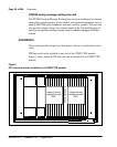
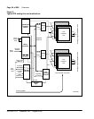
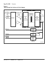
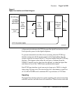
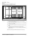
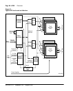
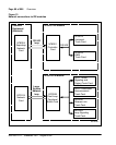
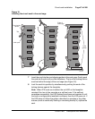
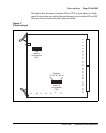
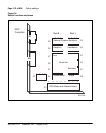
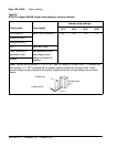
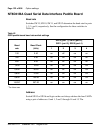
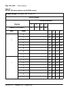
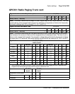
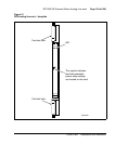
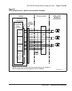
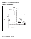
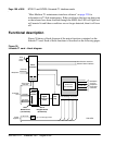
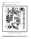
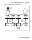
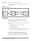
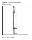
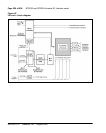
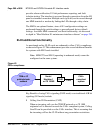
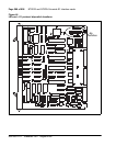
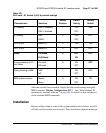
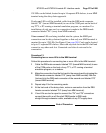
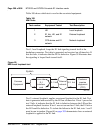
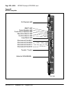
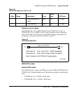
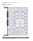
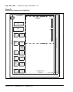
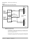
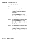
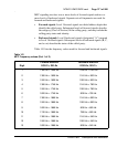
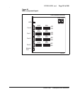
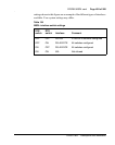
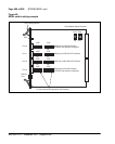
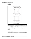
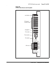
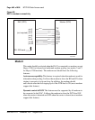
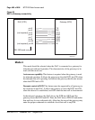
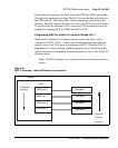
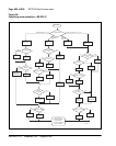
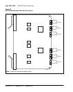
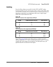
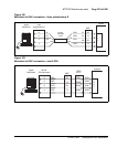
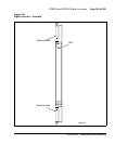
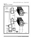
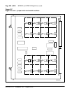
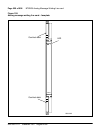
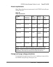
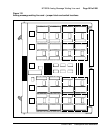
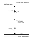
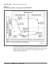
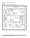
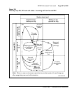
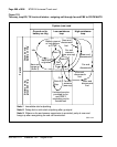
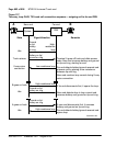
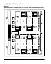
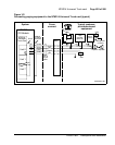
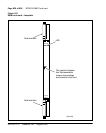
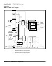
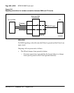
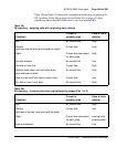
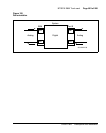
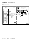
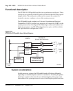
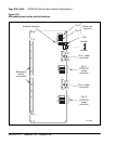
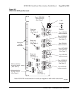
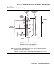
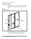
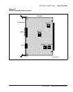
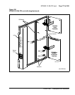
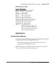
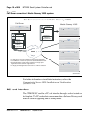
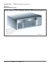
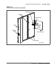
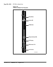
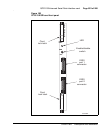
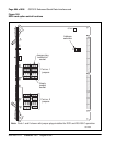
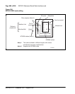
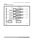
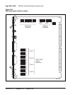
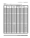
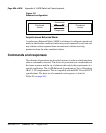
I/O panel connections
Operations aside from PRI require cable connections to the I/O panel.
Connections between the I/O panel and Application Equipment Modules
(AEM) are described in “Application Module description,” Meridian Link
description (553-3201-110).
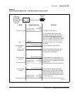
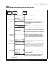
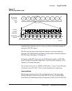
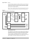
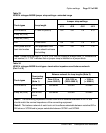
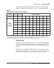
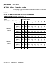
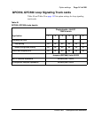
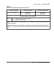
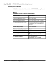
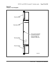
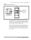
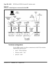
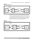
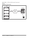
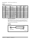
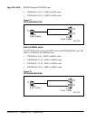
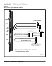
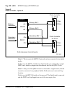
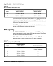
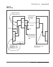
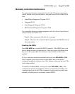
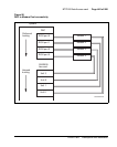
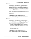
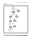
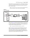
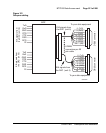
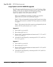
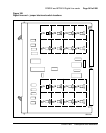
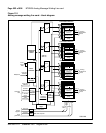
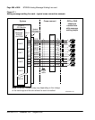
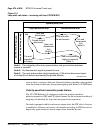
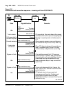
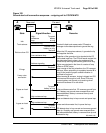
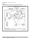
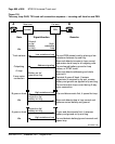
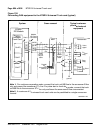
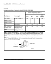
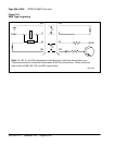
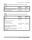
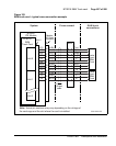
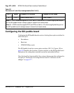
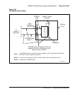
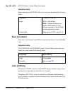
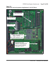
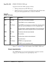
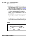
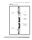
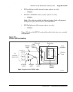
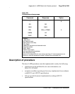
Procedure 18
Cabling the MSDL card to the I/O panel
The following steps explain the procedure for cable connection:
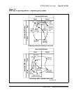
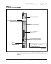
1 Identify the MSDL card and the I/O panel connector to be linked.
2 Using the NTND27AB cable, plug the 26-pin SCSI II male connector end
of a cable into the appropriate MSDL port.
3 Route the cable to the rear of the module next to the I/O panel.
4 Plug the DB25 male connector end of a cable into a DB25 female
connector at the back of the I/O panel.
5 Secure cable connectors in place with their fasteners.
6 Repeat steps 1 through 5 for each connection.
End of Procedure