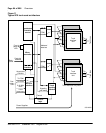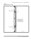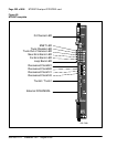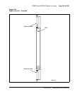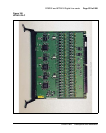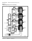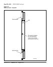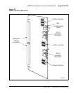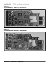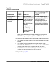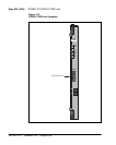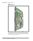
Page 204 of 906 NT5D11 and NT5D14 Lineside T1 Interface cards
553-3001-211 Standard 3.00 August 2005
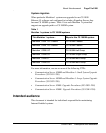
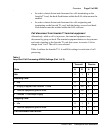
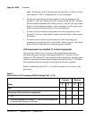
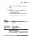
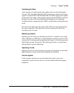
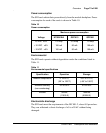
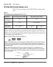
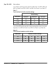
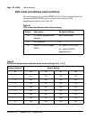
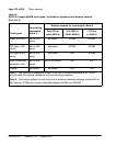
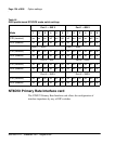
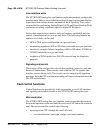
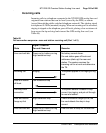
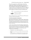
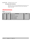
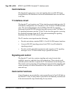
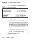
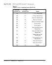
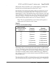
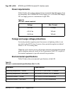
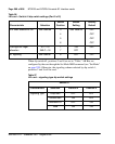
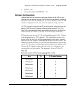
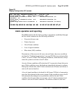
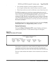
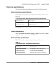
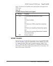
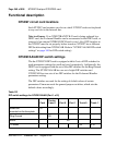
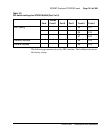
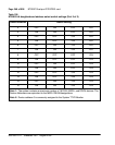
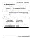
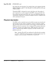
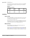
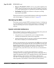
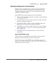
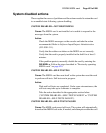
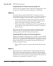
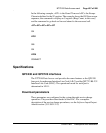
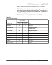
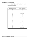
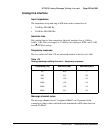
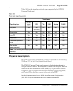
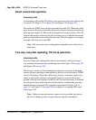
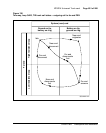
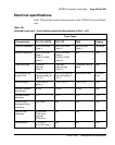
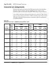
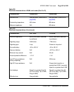
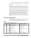
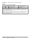
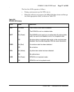
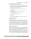
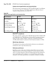
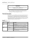
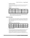
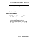
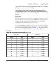
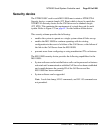
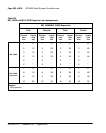
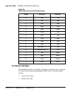
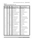
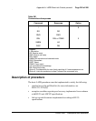
Environmental specifications
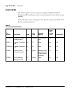
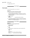
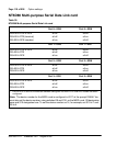
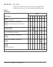
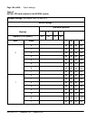
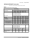
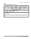
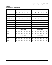
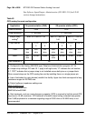
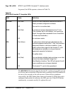
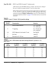
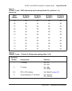
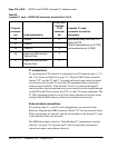
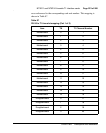
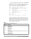
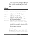
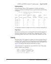
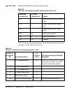
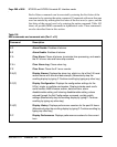
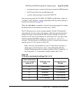
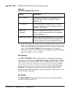
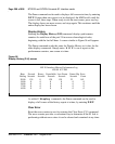
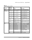
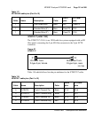
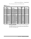
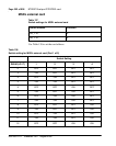
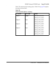
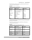
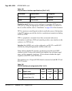
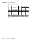
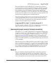
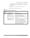
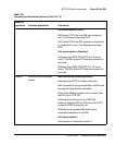
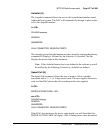
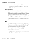
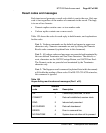
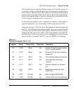
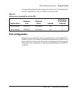
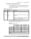
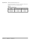
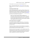
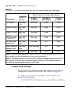
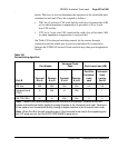
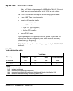
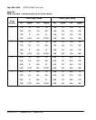
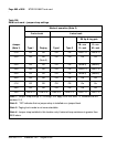
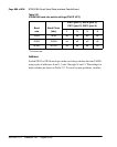
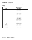
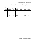
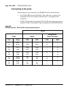
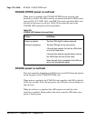
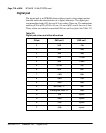
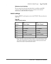
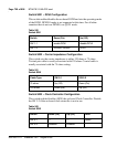
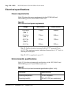
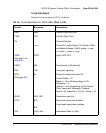
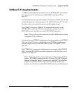
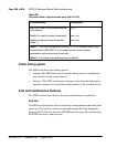
Table 79 lists the environmental specifications of the lineside T1 card.
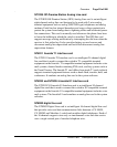
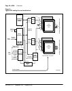
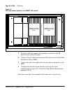
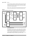
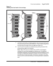
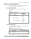
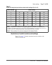
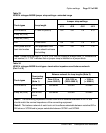
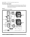
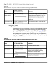
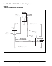
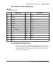
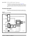
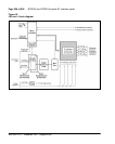
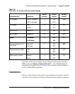
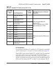
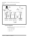
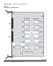
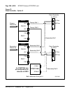
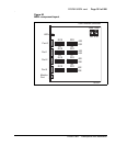
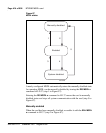
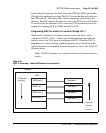
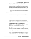
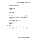
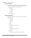
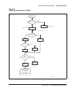
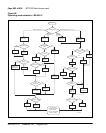
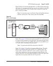
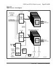
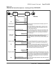
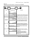
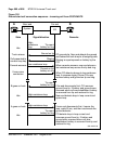
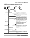
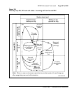
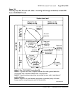
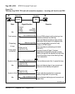
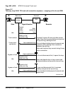
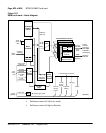
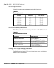
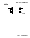
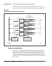
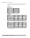
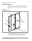
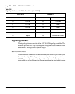
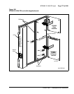
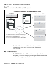
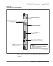
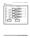
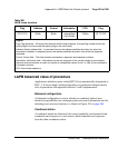
Installation and configuration
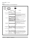
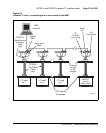
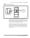
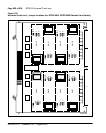
Installation and configuration of the lineside T1 card consists of six basic
steps:
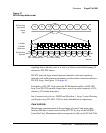
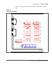
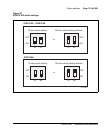
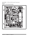
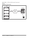
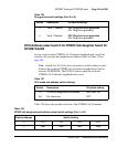
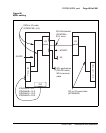
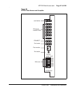
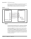
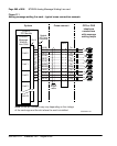
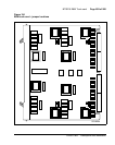
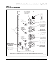
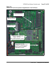
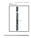
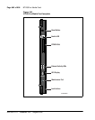
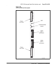
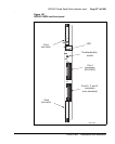
1 Configure the dip switches on the lineside T1 card for the environment.
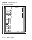
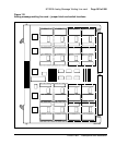
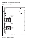
2 Install the lineside T1 card into the selected card slots in the IPE shelf.
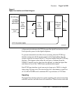
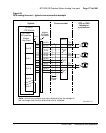
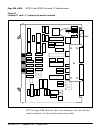
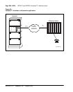
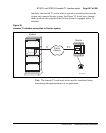
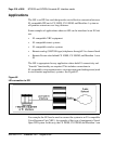
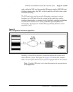
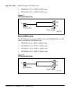
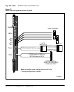
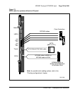
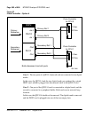
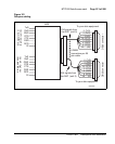
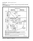
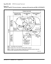
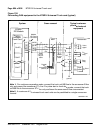
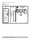
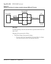
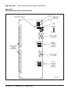
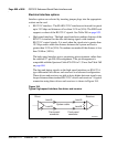
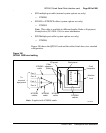
3 Cable from the I/O panel to the Customer Premise Equipment (CPE) or
CSU, MMI terminal or modem (optional), external alarm (optional), and
other lineside T1 cards for daisy chaining use of MMI terminal
(optional).
4 Configure the MMI terminal.
5 Configure the lineside T1 card through the system software and verify
self-test results.
6 Verify initial T1 operation and configure MMI (optional).
Steps 1-5 are explained in this section. Step 6 is covered in “Man-Machine T1
maintenance interface software” on page 225.
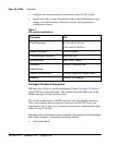
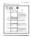
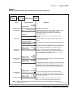
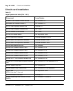
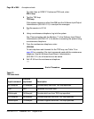
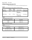
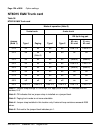
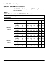
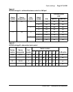
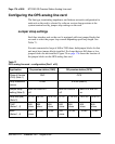
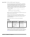
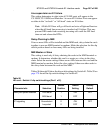
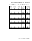
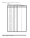
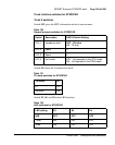
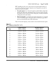
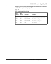
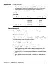
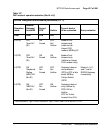
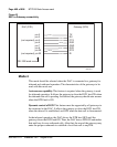
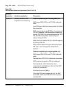
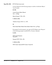
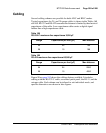
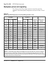
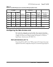
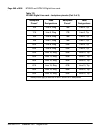
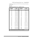
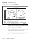
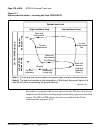
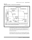
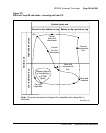
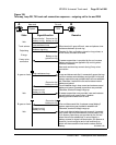
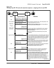
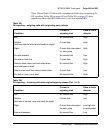
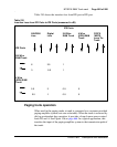
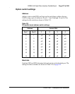
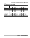
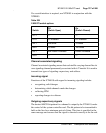
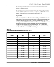
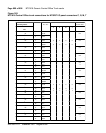
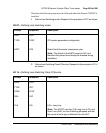
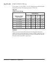
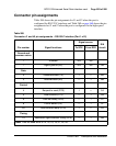
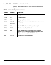
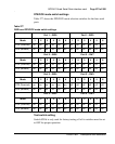
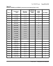
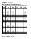
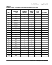
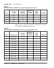
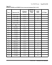
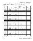
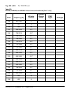
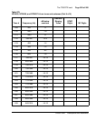
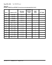
Table 79
Lineside T1 card – environmental specifications
Parameter Specifications
Operating temperature-normal 15° to +30° C (+59° to 86°F), ambient
Operating temperature-short term 10° to +45° C (+50° to 113°F), ambient
Operating humidity-normal 20% to 55% RH (non-condensing)
Operating humidity-short term 20% to 80% RH (non-condensing)
Storage temperature –50° to +70° C (–58° to 158°F), ambient
Storage humidity 5% to 95% RH (non-condensing)