Page 400 of 906 NT6D80 MSDL card
553-3001-211 Standard 3.00 August 2005
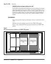
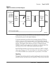
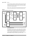
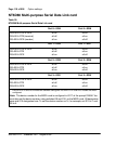
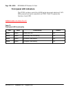
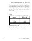
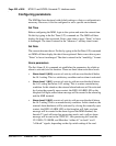
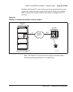
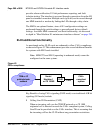
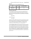
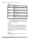
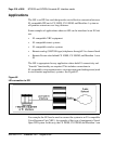
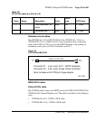
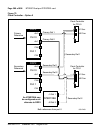
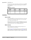
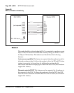
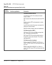
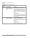
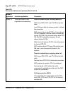
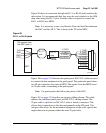
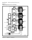
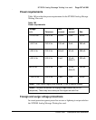
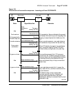
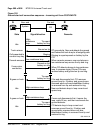
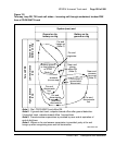
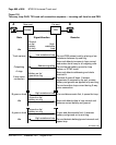
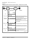
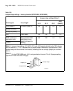
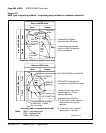
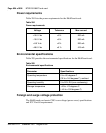
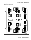
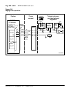
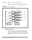
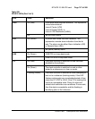
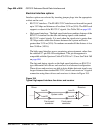
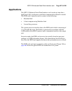
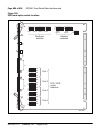
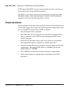
Emulation mode Each port can be configured to emulate a DCE port or a
DTE port by setting the appropriate switches on the MSDL. For details on
how to set the switches, refer to “Installation” on page 404 of this document.
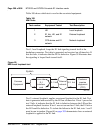
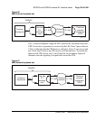
DCE is a master or controlling device that is usually the source of information
to the DTE and may provide the clock in a synchronous transmission linking
a DCE to a DTE.
DTE is a peripheral or terminal device that can transmit and receive
information to and from a DCE and normally provides a user interface to the
system or to a DCE device.
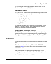
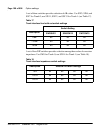
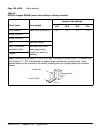
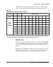
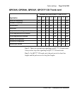
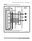
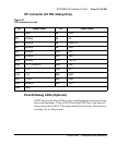
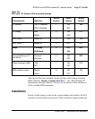
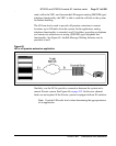
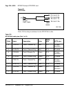
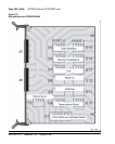
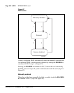
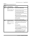
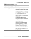
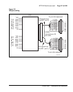
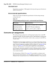
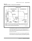
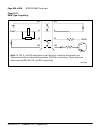
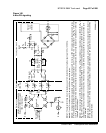
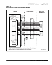
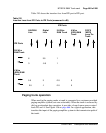
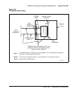
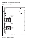
Interface Each MSDL port can be configured as an RS-232 or an RS-422
interface by setting the appropriate switches on the card.
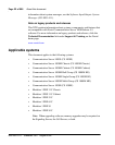
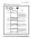
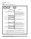
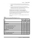
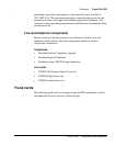
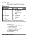
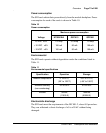
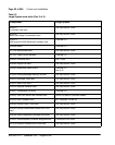
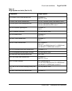
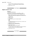
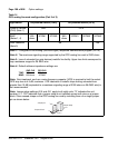
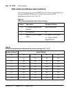
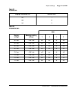
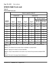
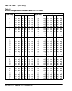
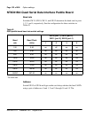
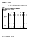
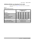
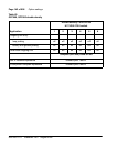
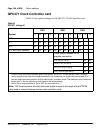
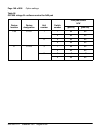
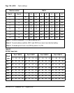
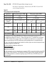
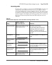
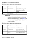
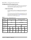
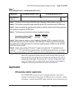
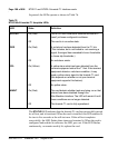
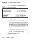
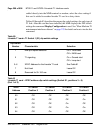
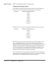
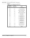
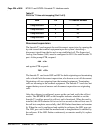
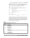
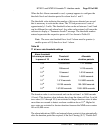
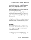
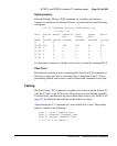
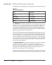
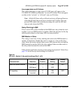
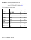
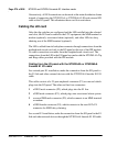
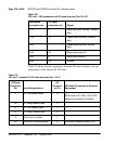
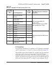
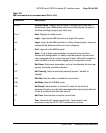
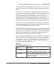
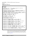
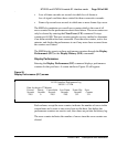
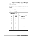
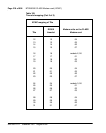
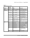
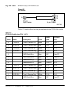
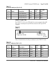
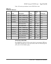
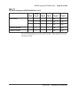
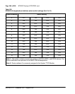
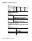
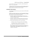
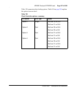
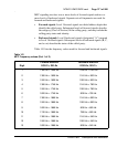
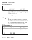
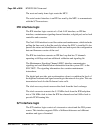
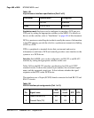
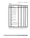
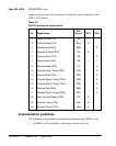
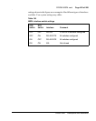
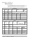
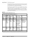
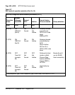
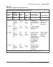
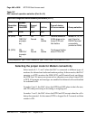
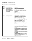
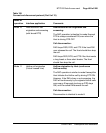
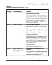
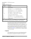
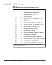
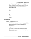
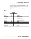
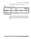
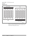
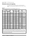
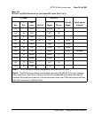
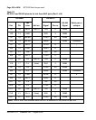
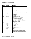
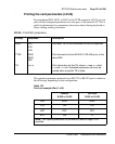
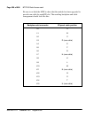
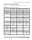
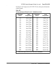
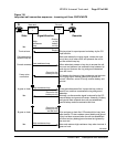
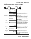
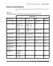
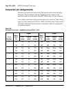
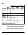
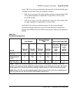
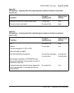
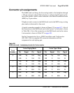
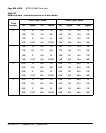
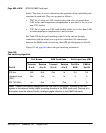
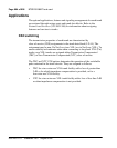
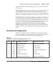
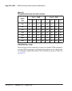
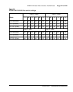
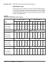
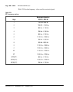
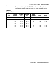
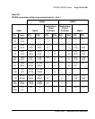
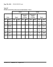
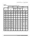
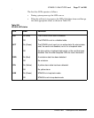
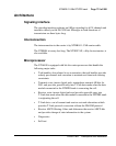
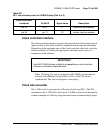
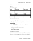
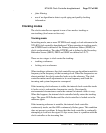
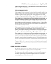
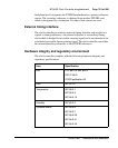
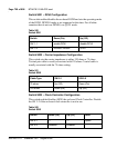
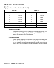
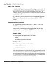
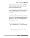
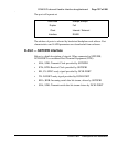
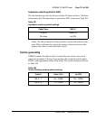
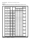
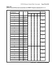
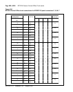
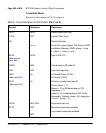
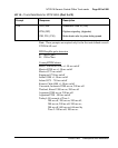
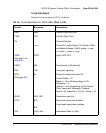
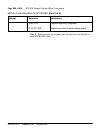
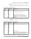
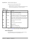
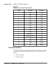
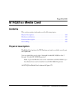
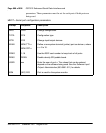
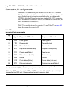
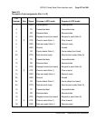
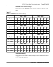
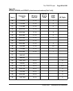
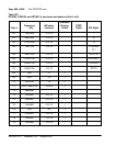
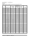
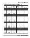
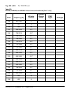
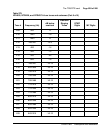
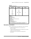
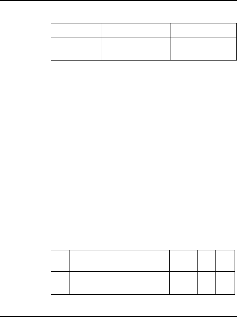
Table 150 lists the RS-232 interface specifications for EIA and CCITT
standard circuits. It shows the connector pin number, the associated signal
name, and the supported circuit type. It also indicates whether the signal
originates at the DTE or the DCE device.
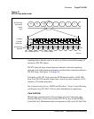
This interface uses a 26-pin (SCSI II) female connector for both RS-232 and
RS-422 circuits.
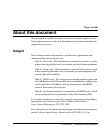
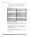
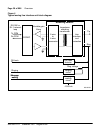
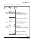
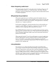
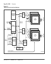
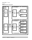
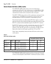
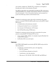
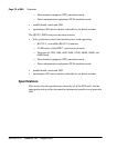
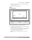
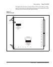
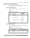
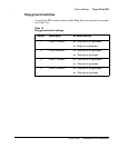
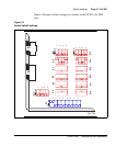
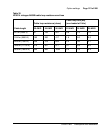
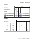
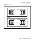
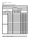
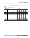
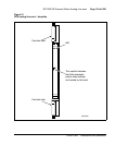
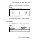
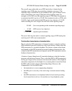
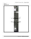
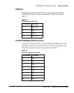
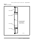
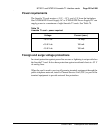
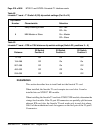
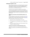
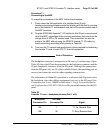
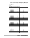
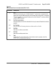
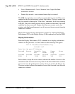
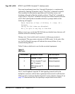
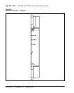
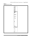
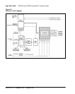
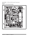
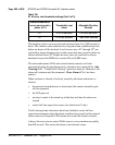
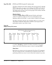
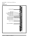
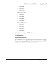
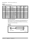
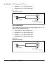
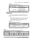
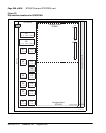
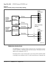
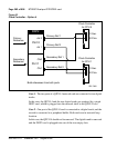
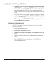
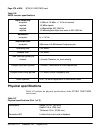
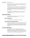
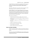
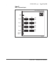
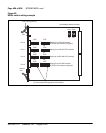
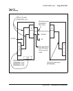
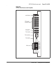
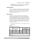
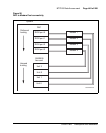
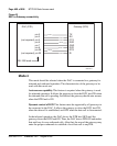
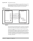
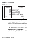
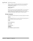
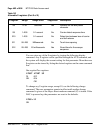
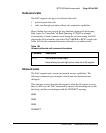
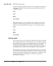
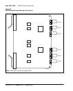
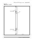
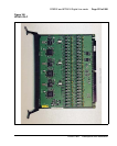
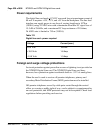
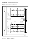
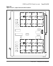
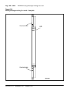
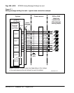
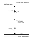
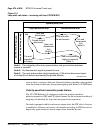
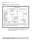
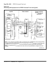
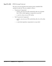
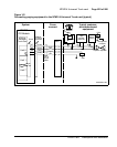
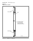
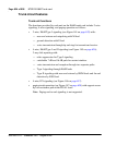
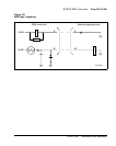
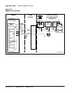
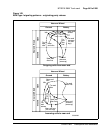
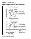
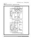
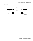
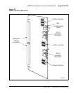
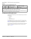
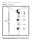
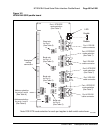
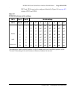
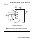
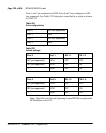
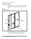
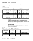
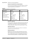
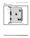
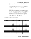
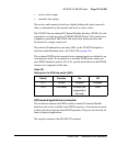
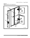
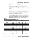
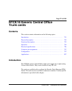
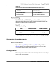
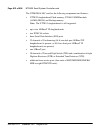
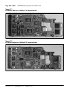
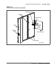
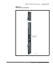
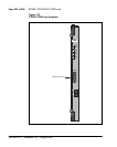
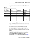
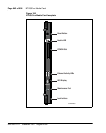
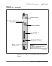
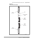
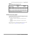
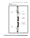
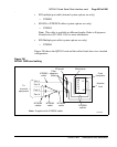
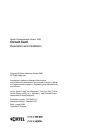
RS-422 Switches
Mode DTE or DCE Switches
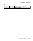
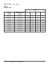
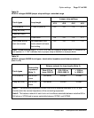
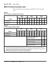
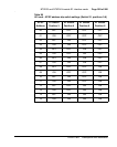
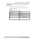
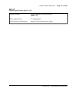
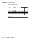
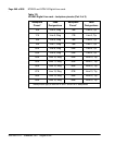
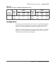
Table 150
RS-232 interface pin assignments (Part 1 of 2)
Pin Signal name
EIA
circuit
CCITT
circuit DTE DCE
1 Frame Ground (FG) AA 102 — —
2 Transmit Data (TX) BA 103 X
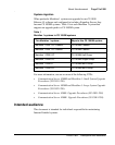
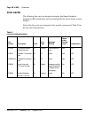
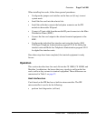
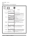
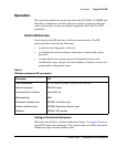
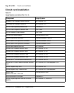
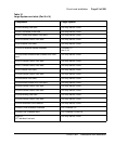
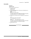
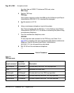
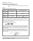
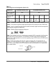
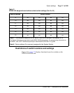
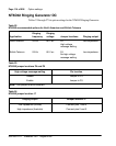
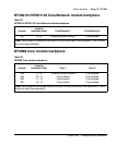
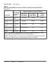
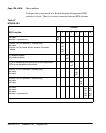
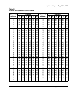
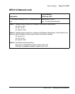
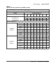
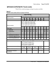
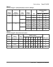
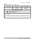
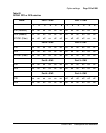
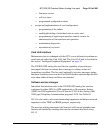
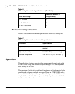
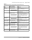
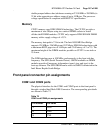
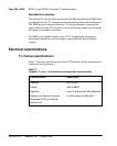
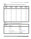
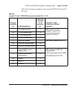
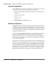
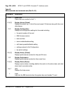
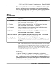
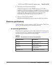
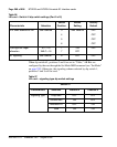
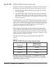
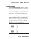
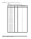
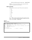
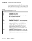
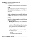
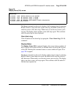
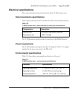
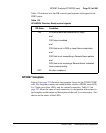
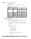
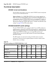
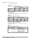
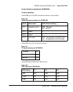
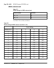
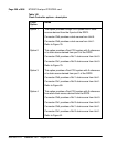
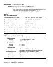
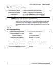
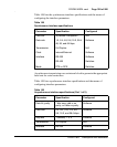
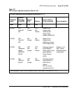
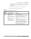
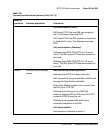
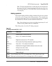
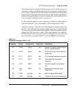
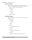
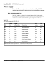
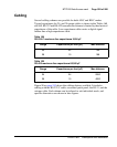
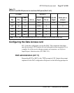
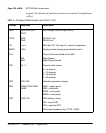
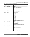
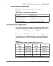
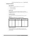
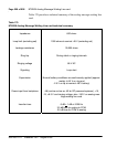
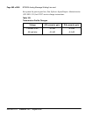
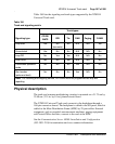
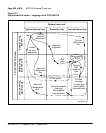
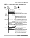
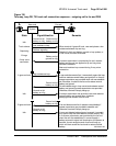
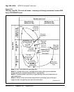
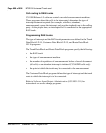
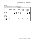
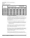
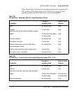
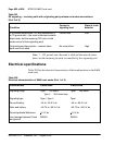
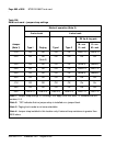
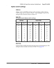
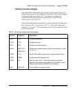
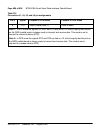
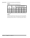
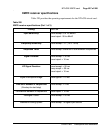
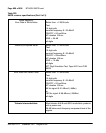
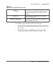
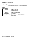
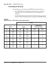
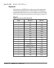
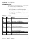
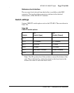
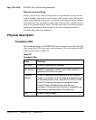
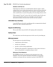
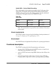
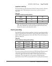
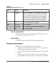
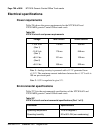
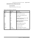
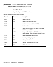
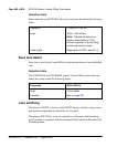
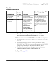
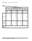
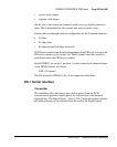
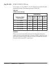
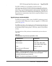
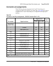
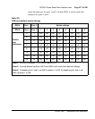
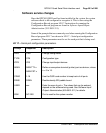
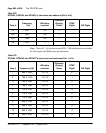
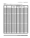
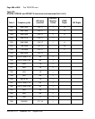
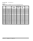
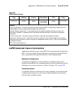
Table 149
Asynchronous interface specifications (Part 2 of 2)
Parameter Specification Configured