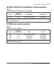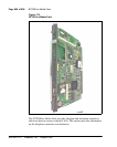
Page 874 of 906 QPC841 Quad Serial Data Interface card
553-3001-211 Standard 3.00 August 2005
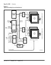
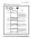
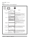
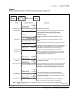
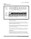
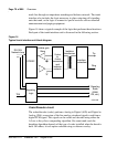
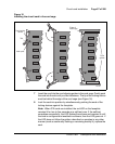
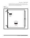
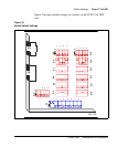
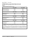
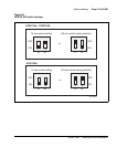
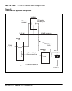
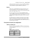
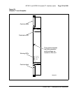
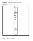
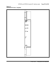
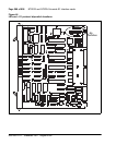
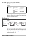
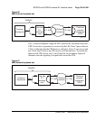
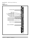
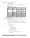
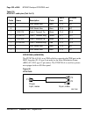
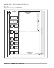
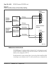
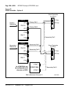
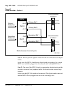
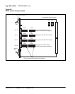
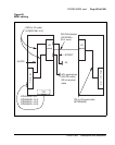
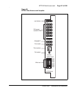
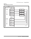
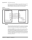
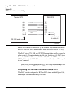
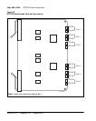
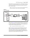
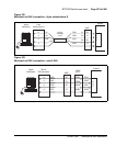
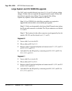
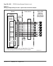
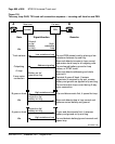
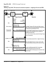
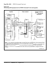
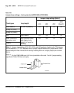
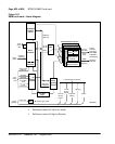
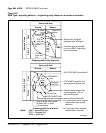
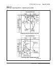
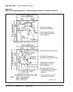
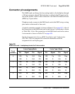
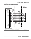
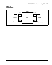
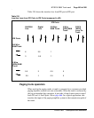
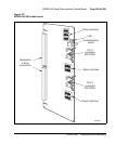
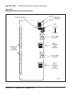
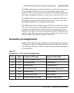
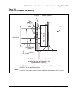
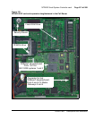
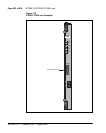
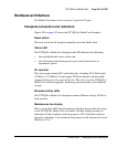
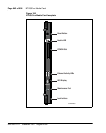
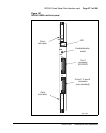
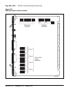
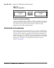
Connector pin assignments
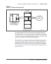
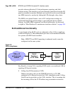
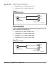
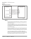
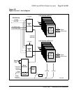
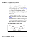
Connector J1 is connected to port one, and uses the RS-232-C standard
DB-25 pinout. Connector J2 is connected to ports two, three, and four, and is
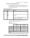
a non-standard pinout that requires an adapter cable. An adapter cable
(NT8D96) splits the J2 signals out to three standard RS-232-C connectors.
Port 2 is connected to connector A, Port 3 is connected to connector B, and
Port 4 is connected to connector C.
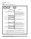
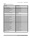
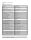
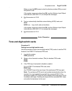
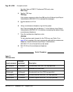
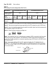
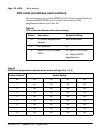
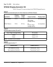
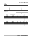
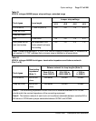
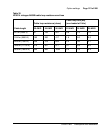
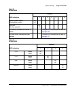
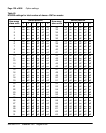
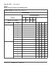
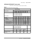
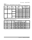
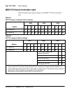
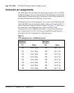
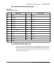
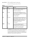
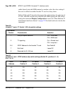
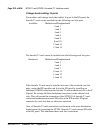
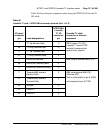
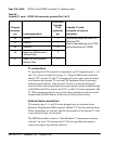
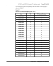
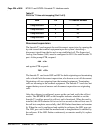
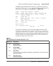
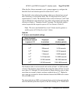
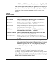
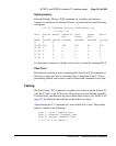
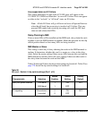
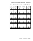
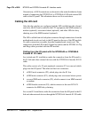
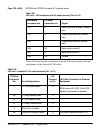
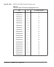
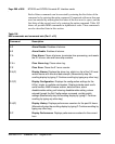
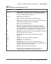
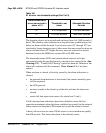
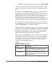
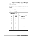
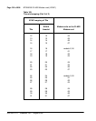
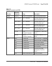
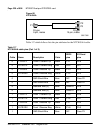
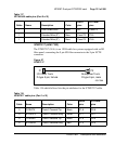
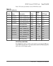
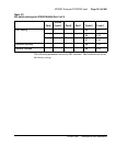
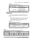
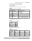
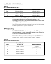
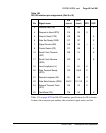
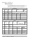
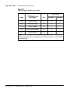
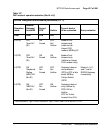
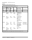
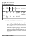
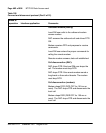
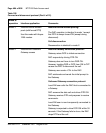
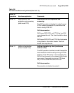
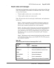
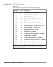
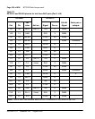
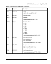
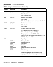
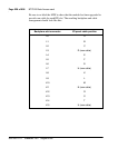
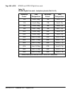
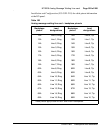
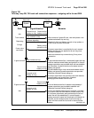
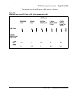
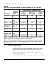
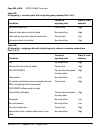
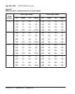
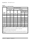
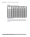
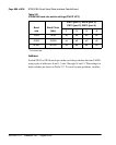
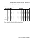
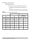
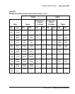
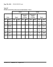
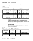
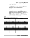
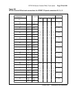
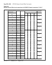
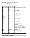
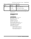
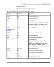
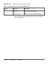
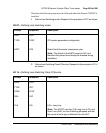
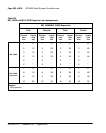
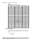
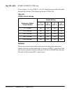
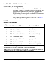
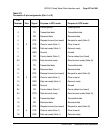
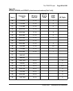
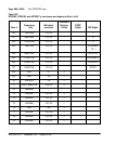
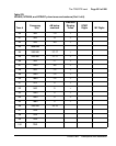
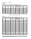
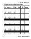
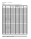
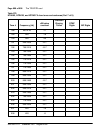
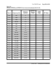
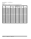
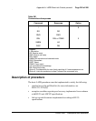
Table 273 shows the pinouts for connector J1, and Table 274 on page 875
shows the pinouts for connector J2.
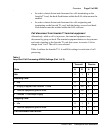
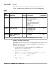
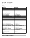
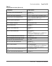
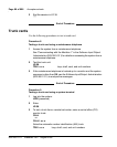
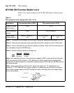
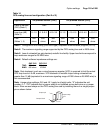
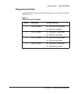
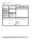
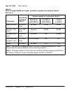
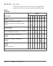
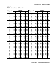
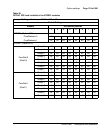
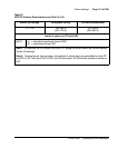
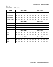
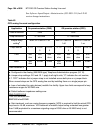
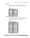
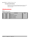
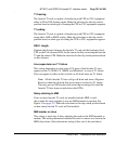
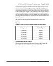
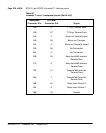
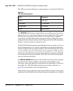
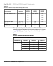
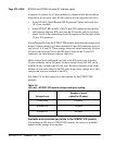
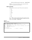
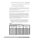
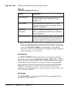
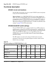
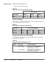
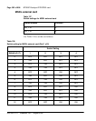
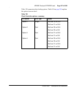
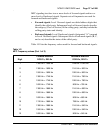
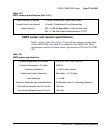
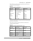
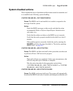
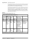
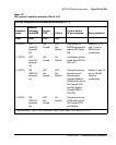
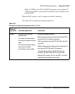
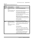
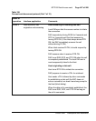
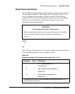
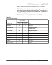
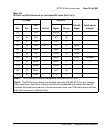
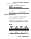
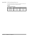
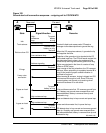
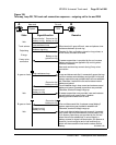
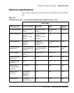
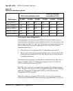
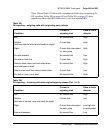
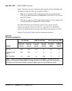
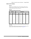
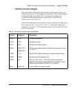
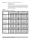
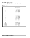
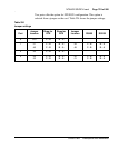
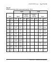
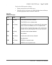
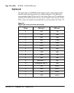
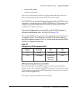
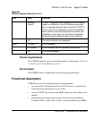
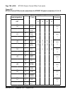
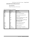
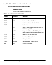
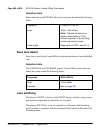
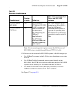
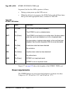
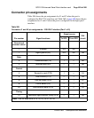
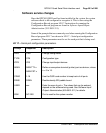
Table 273
Connector J1 pin assignments
Pin
number
Signal Purpose in DTE mode Purpose in DCE mode
1 FGD Frame ground Frame ground
2 TD Received data Transmitted data
3 RD Transmitted data Received data
4 RTS Request to send (not used) Request to send (Note 2)
5 CTS Clear to send (Note 1) Clear to send
6 DSR Data set ready (Note 1) Data set ready
7 GND Ground Ground
8 CD Carrier detect (Note 1) Carrier detect (not used)
20 DTR Data terminal ready Data terminal ready (Note 2)
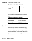
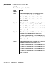
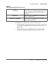
Note 1: In DTE mode, the signals CD, DSR, and CTS are tied to +12 volts (through a resistor)
to indicate that the QSDI port is always ready to transmit and receive data.
Note 2: In DCE mode, the signals DTR, and RTS are tied to +12 volts (through a resistor) to
indicate that the QSDI port is always ready to transmit and receive data.