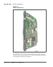
NT7D16 Data Access card Page 525 of 906
Circuit Card Description and Installation
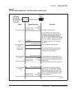
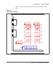
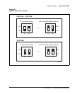
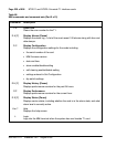
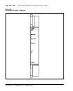
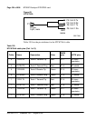
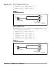
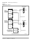
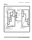
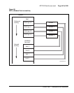
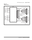
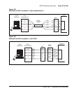
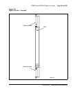
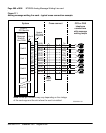
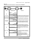
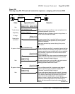
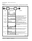
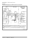
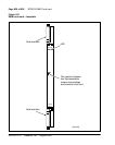
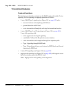
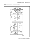
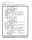
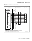
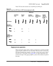
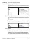
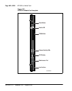
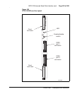
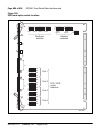
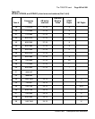
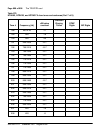
Segment 2
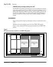
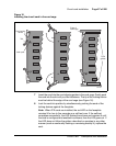
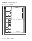
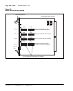
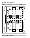
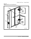
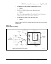
1 Leave cable K as is in slot L8.
2 Move cable end L-3 to L9-3.
3 Remove cable M from the backplane and connect ends M-1, M-2, and
M-3 to L10-1, L10-2, and L10-3.
4 Add cable N to the I/O panel by connecting ends N-1, N-2, and N-3 to
L11-1, L11-2, and L11-3.
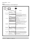
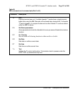
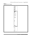
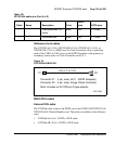
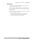
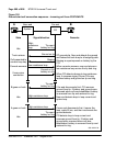
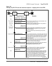
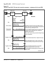
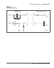
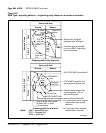
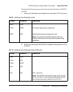
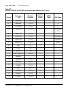
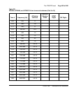
Segment 3
1 Leave cable R as is in slot L12.
2 Move cable end S-3 to L13-3.
3 Remove cable T from the backplane and connect ends T-1, T-2, and T-3
to L14-1, L14-2, and L14-3.
4 Add cable U to the I/O panel by connecting ends U-1, U-2, and U-3 to
L15-1, L15-2, and L15-3.