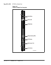
NTAK10 2.0 Mb DTI card Page 723 of 906
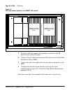
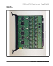
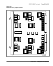
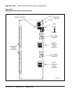
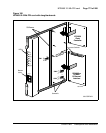
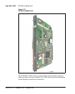
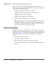
Circuit Card Description and Installation
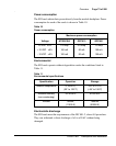
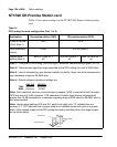
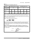
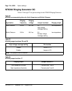
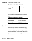
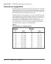
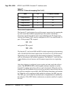
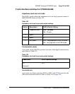
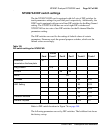
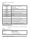
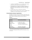
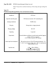
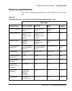
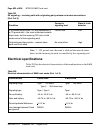
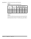
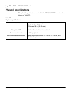
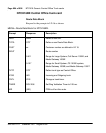
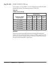
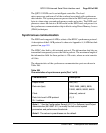
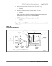
Power requirements
The 2MB DTI obtains its power from the backplane. It draws less than 2 A
on +5 V, 50 mA on +15 V and 50 mA on –15 V.
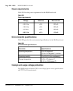
Environment
The NTAK10 card meets all applicable Nortel operating specifications.
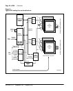
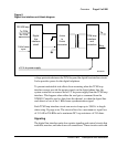
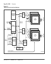
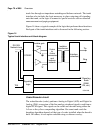
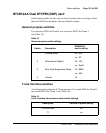
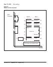
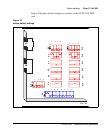
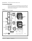
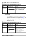
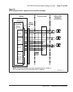
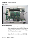
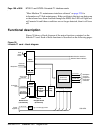
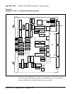
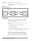
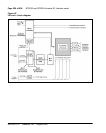
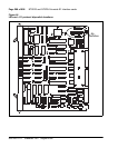
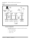
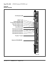
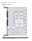
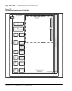
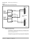
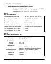
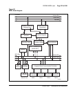
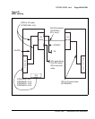
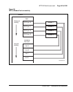
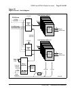
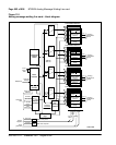
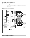
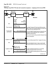
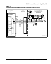
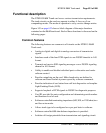
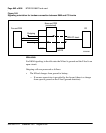
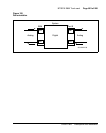
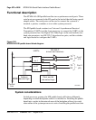
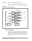
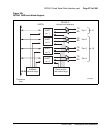
Functional description
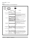
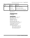
The NTAK10 provides the following features and functions:
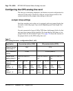
• a clock controller that can be switched in as an option
• software-selectable A/µlaw operation
• software-selectable digital pads on a per channel basis
• frame alignment and multiframe alignment detection
• frame and multiframe pattern generation
• CRC-4 transmission and reception (software selectable)
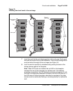
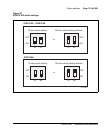
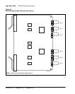
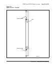
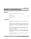
• card status and alarm indication with faceplate-mounted LEDs
• Periodic Pulse Metering (PPM) counting
• outpulsing of digits on any of the ABCD bits
• Card-LAN for maintenance communication
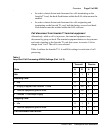
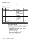
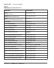
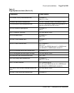
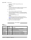
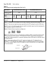
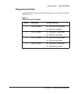
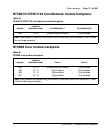
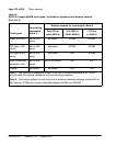
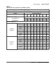
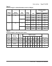
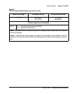
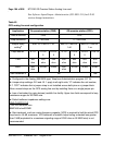
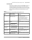
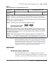
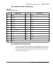
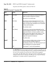
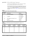
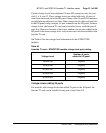
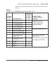
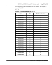
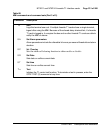
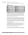
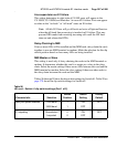
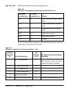
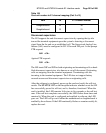
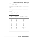
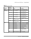
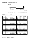
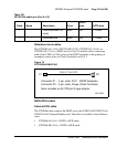
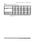
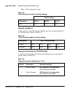
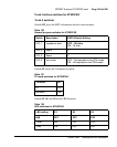
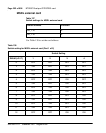
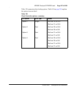
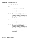
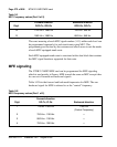
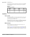
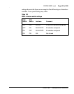
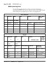
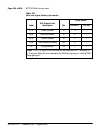
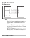
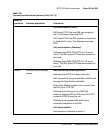
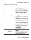
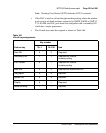
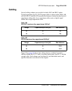
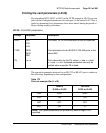
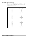
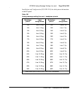
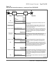
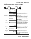
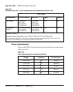
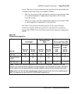
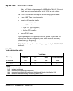
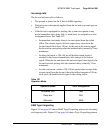
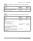
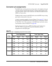
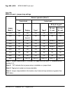
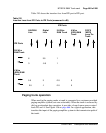
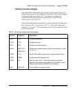
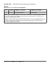
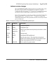
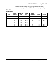
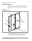
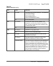
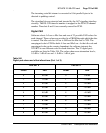
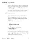
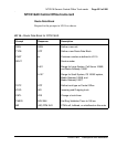
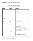
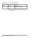
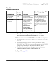
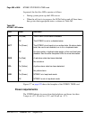
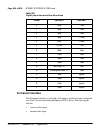
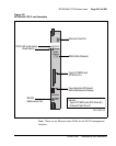
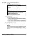
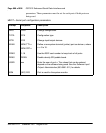
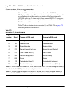
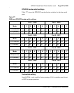
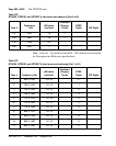
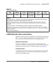
Flashing
(Green)
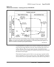
The clock controller is switched on and locking onto the
primary reference.
Off The clock controller is switched off.
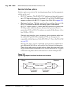
Note: See “Clock controller interface” on page 729 in this
chapter for more on tracking and free-run operation.
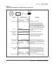
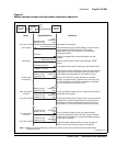
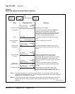
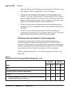
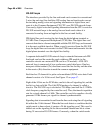
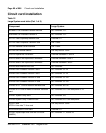
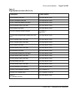
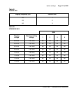
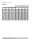
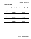
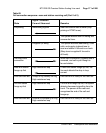
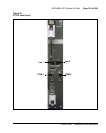
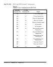
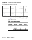
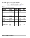
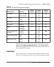
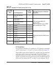
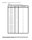
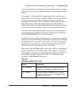
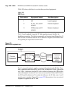
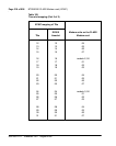
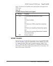
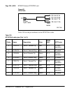
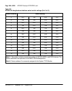
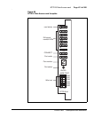
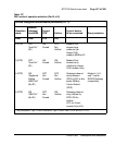
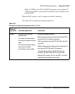
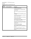
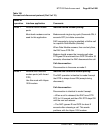
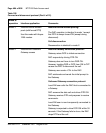
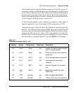
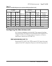
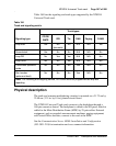
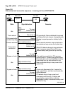
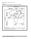
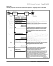
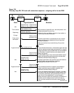
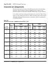
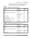
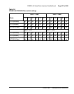
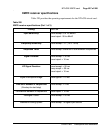
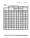
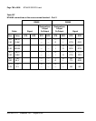
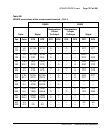
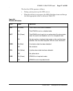
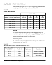
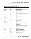
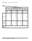
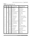
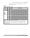
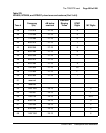
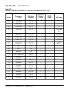
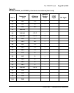
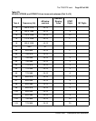
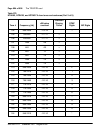
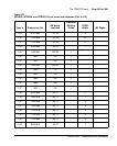
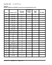
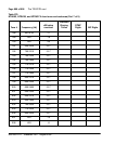
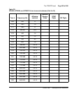
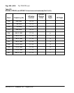
Table 234
NTAK10 LED states (Part 2 of 2)
LED State Definition