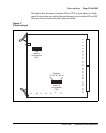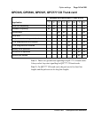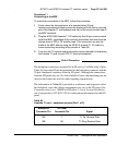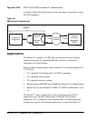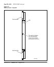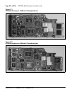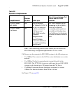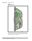
Page 172 of 906 NT1R20 Off-Premise Station Analog Line card
553-3001-211 Standard 3.00 August 2005
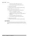
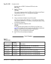
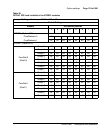
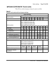
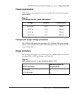
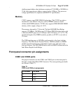
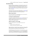
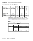
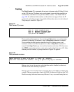
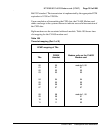
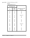
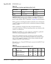
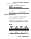
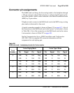
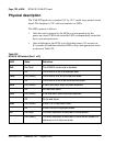
Connector pin assignments
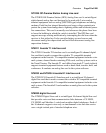
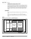
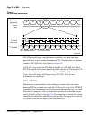
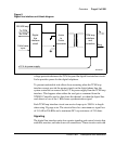
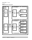
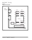
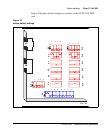
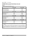
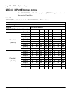
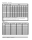
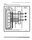
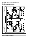
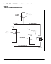
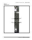
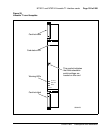
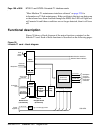
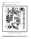
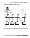
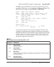
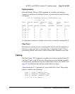
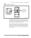
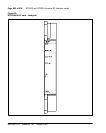
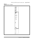
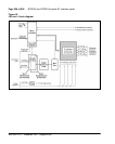
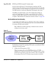
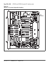
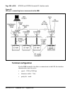
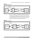
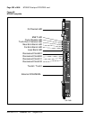
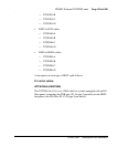
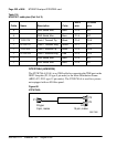
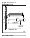
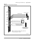
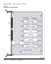
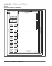
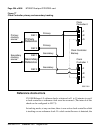
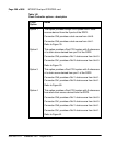
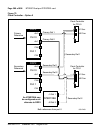
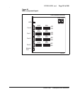
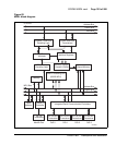
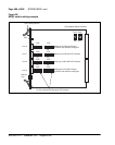
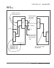
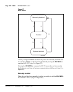
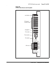
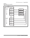
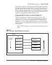
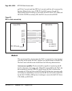
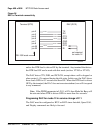
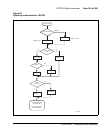
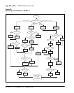
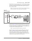
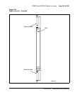
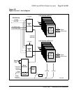
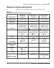
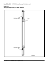
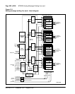
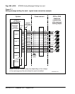
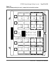
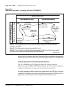
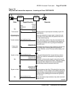
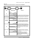
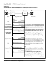
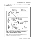
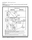
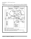
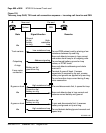
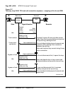
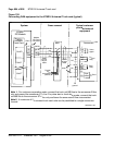
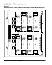
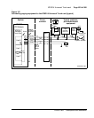
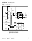
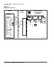
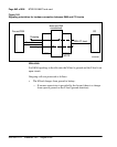
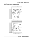
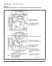
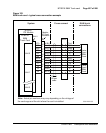
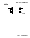
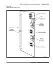
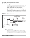
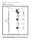
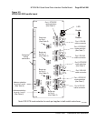
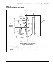
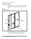
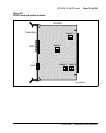
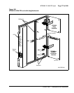
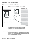
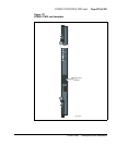
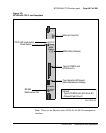
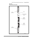
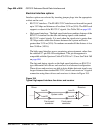
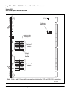
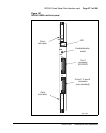
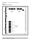
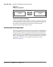
The OPS analog line card brings the eight analog telephone lines to the IPE
backplane through a 160-pin connector shroud. The backplane is cabled to the
input/output (I/O) panel on the rear of the module, which is then connected to
the Main Distribution Frame (MDF) by 25-pair cables.
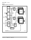
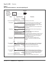
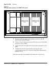
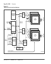
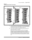
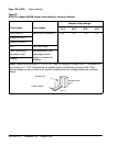
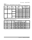
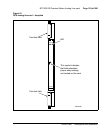
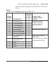
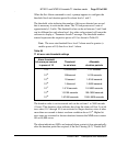
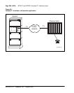
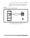
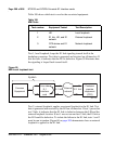
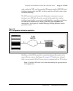
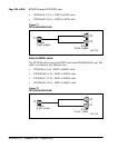
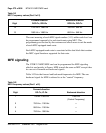
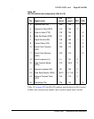
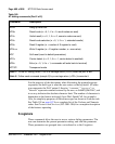
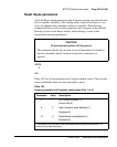
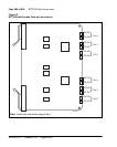
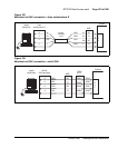
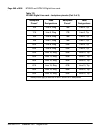
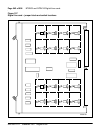
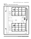
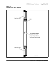
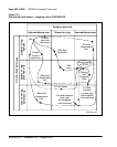
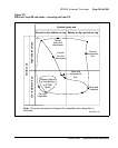
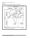
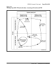
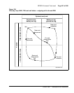
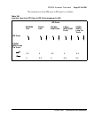
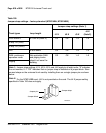
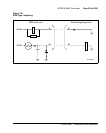
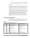
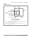
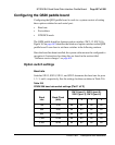
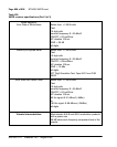
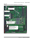
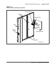
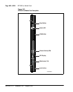
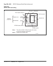
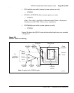
Telephone lines from station equipment cross connect to the OPS analog line
card at the MDF using a wiring plan similar to that used for trunk cards. A
typical connection example is shown in Figure 23 on page 173, and a list of
the connections to the analog line card is shown in Table 70. See
Communication Server 1000M and Meridian 1: Large System Installation
and Configuration (553-3021-210) for more detailed I/O panel connector
information and wire assignments for each tip/ring pair.
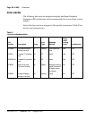
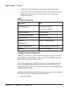
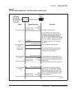
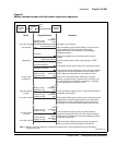
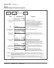
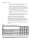
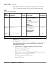
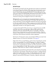
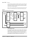
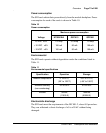
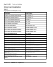
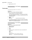
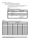
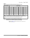
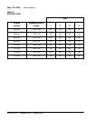
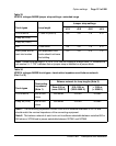
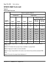
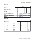
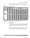
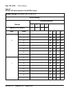
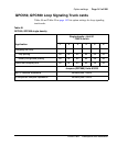
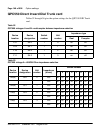
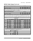
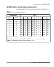
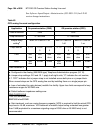
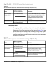
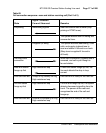
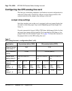
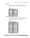
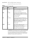
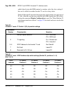
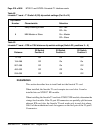
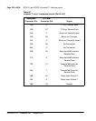
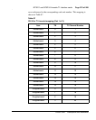
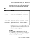
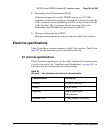
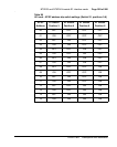
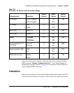
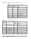
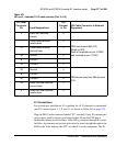
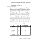
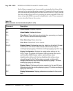
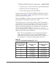
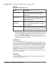
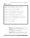
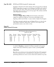
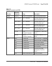
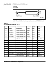
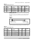
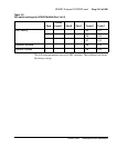
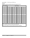
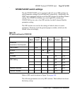
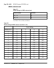
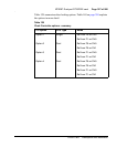
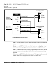
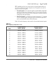
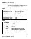
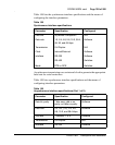
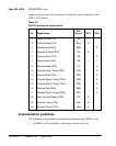
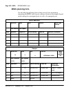
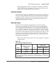
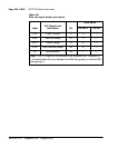
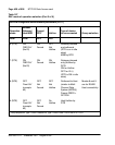
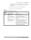
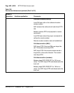
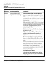
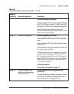
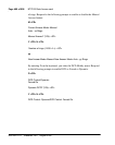
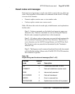
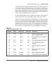
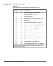
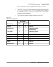
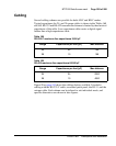
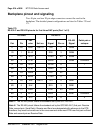
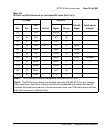
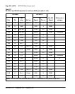
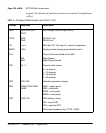
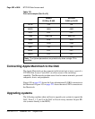
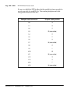
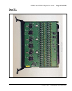
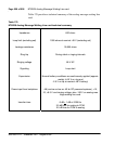
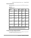
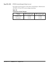
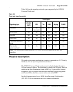
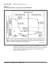
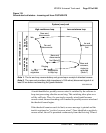
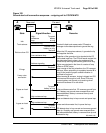
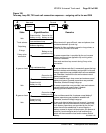
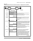
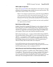
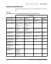
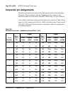
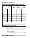
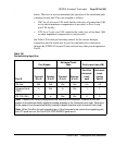
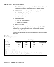
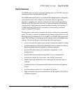
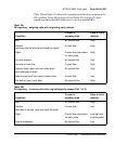
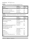
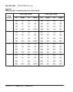
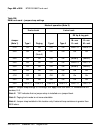
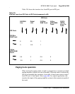
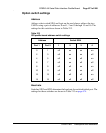
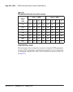
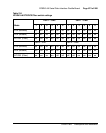
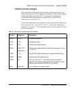
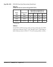
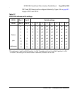
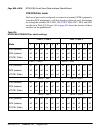
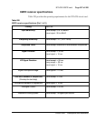
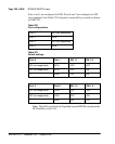
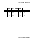
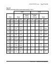
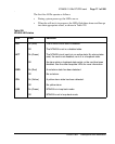
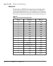
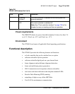
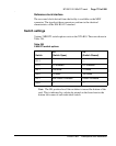
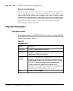
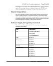
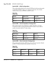
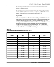
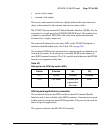
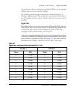
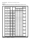
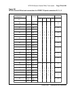
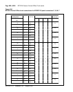
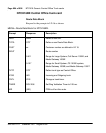
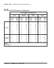
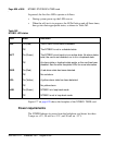
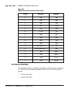
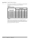
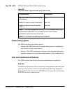
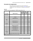
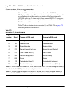
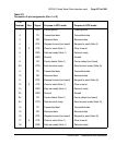
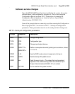
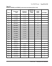
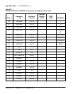
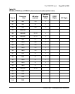
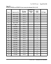
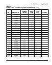
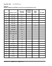
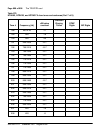
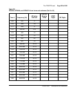
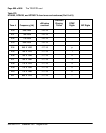
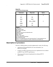
Table 70
OPS analog line card – backplane pinouts
Backplane
Connector
Pin Signal
Backplane
Connector
Pin Signal
12A Unit 0, Ring 12B Unit 0, Tip
13A Unit 1, Ring 13B Unit 1, Tip
14A Unit 2, Ring 14B Unit 2, Tip
15A Unit 3, Ring 15B Unit 3, Tip
16A Unit 4, Ring 16B Unit 4, Tip
17A Unit 5, Ring 17B Unit 5, Tip
18A Unit 6, Ring 18B Unit 6, Tip
19A Unit 7, Ring 19B Unit 7, Tip