Page 150 of 906 Option settings
553-3001-211 Standard 3.00 August 2005
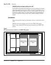
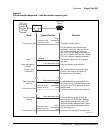
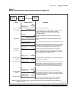
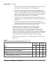
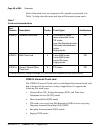
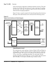
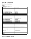
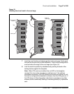
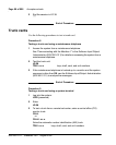
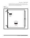
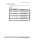
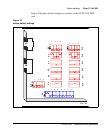
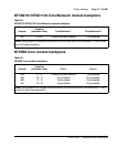
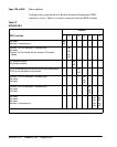
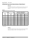
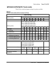
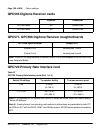
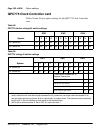
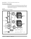
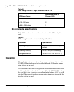
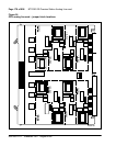
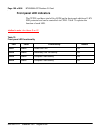
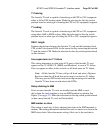
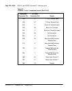
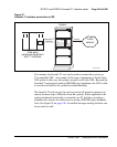
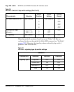
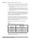
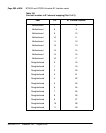
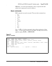
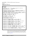
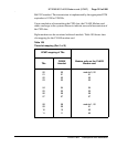
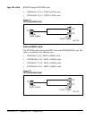
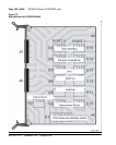
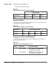
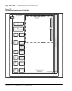
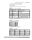
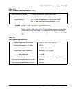
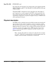
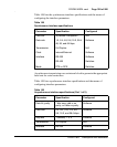
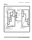
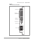
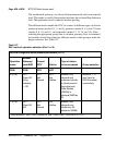
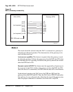
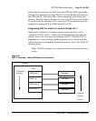
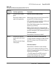
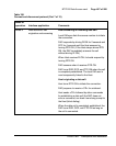
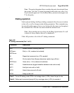
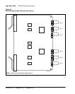
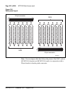
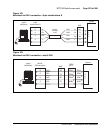
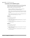
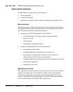
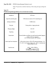
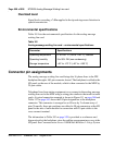
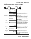
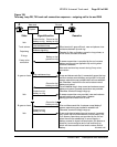
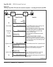
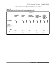
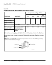
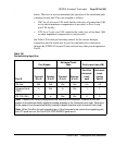
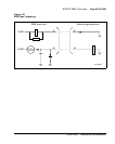
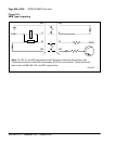
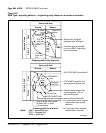
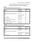
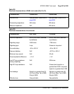
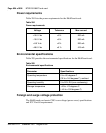
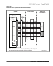
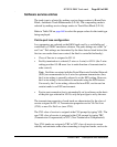
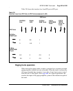
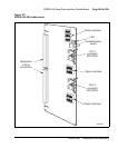
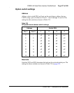
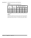
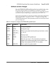
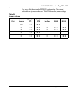
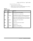
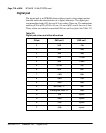
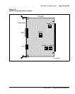
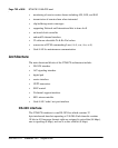
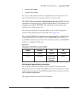
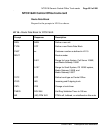
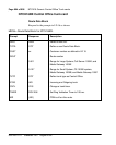
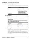
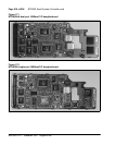
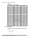
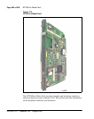
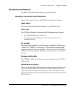
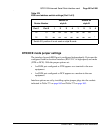
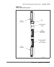
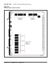
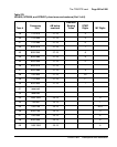
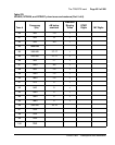
QPC595 Digitone Receiver cards
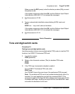
QPC577, QPC596 Digitone Receiver daughterboards
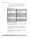
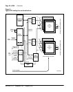
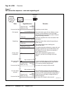
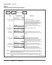
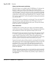
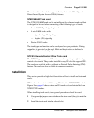
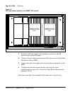
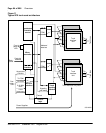
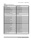
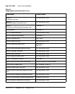
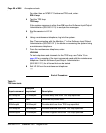
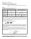
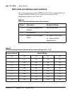
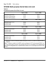
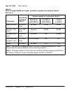
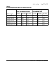
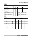
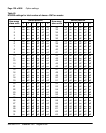
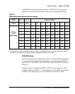
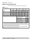
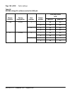
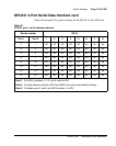
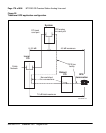
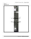
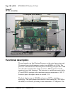
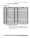
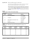
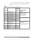
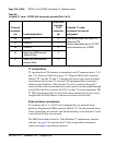
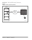
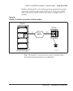
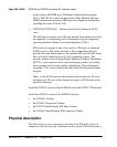
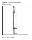
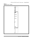
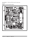
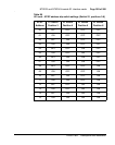
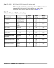
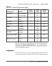
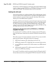
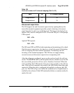
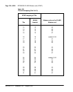
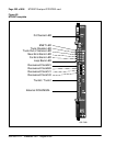
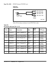
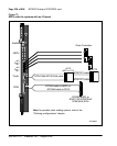
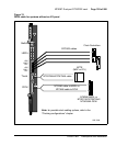
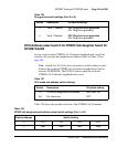
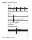
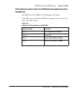
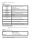
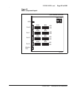
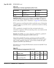
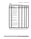
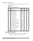
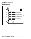
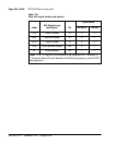
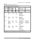
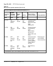
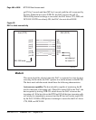
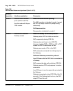
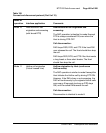
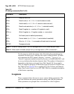
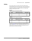
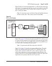
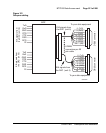
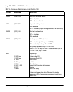
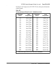
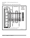
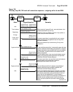
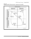
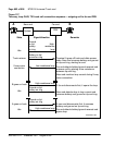
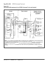
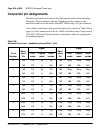
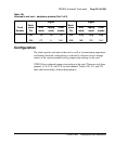
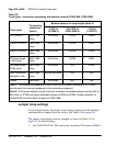
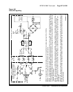
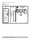
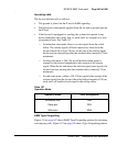
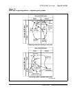
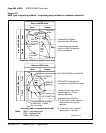
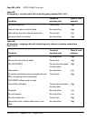
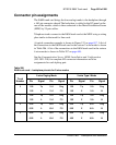
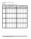
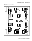
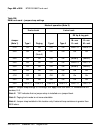
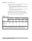
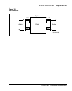
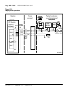
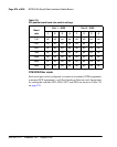
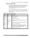
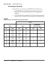
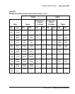
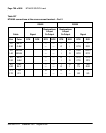
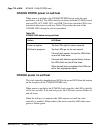
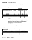
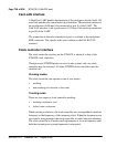
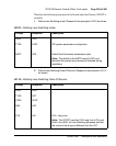
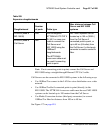
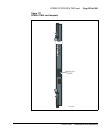
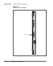
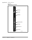
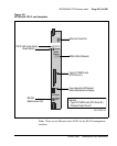
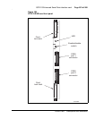
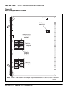
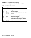
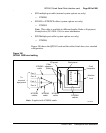
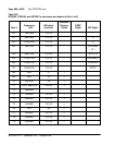
QPC720 Primary Rate Interface card
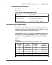
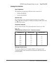
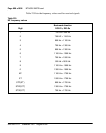
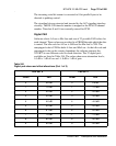
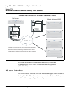
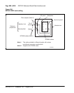
Location Connection
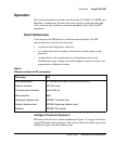
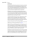
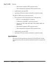
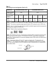
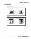
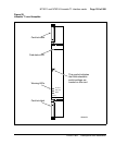
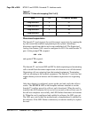
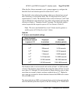
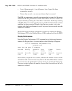
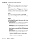
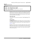
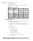
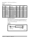
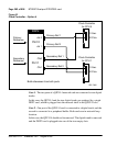
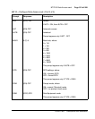
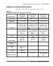
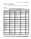
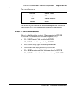
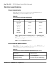
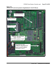
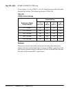
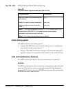
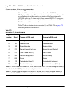
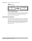
12 DTMF tones E9 Center to E3
16 DTMF tones E9 Center to E2
16/12 tone options jumper Jumper at P1
16 tone (4 x 4) connect pins 1 and 2
12 tone (3 x 4) connect pins 2 and 3
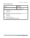
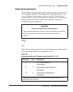
Note: When a DTR daughterboard is installed, check YES on the faceplate of the QPC659 Dual
Loop Peripheral Buffer.
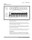
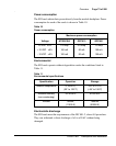
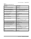
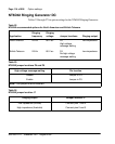
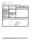
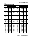
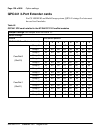
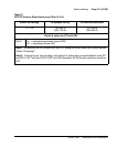
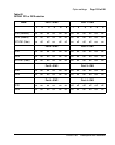
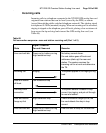
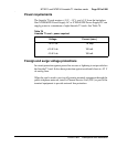
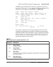
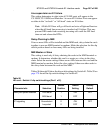
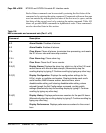
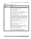
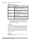
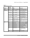
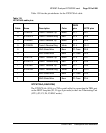
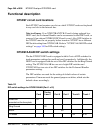
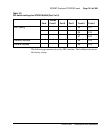
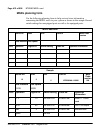
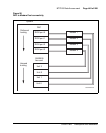
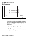
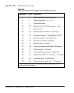
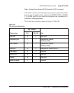
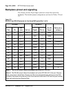
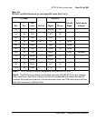
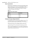
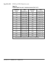
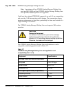
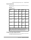
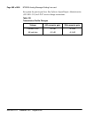
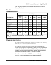
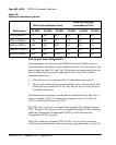
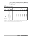
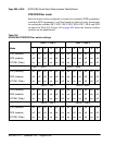
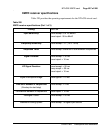
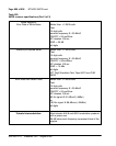
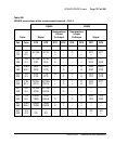
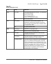
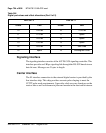
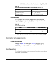
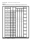
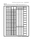
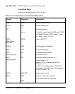
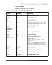
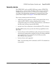
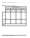
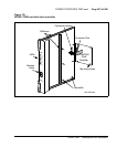
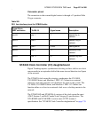
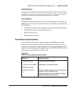
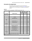
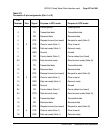
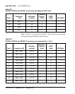
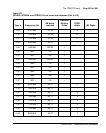
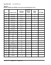
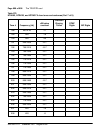
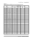
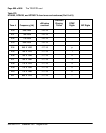
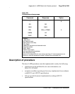
Table 57
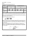
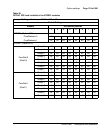
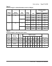
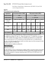
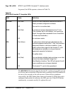
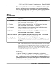
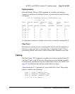
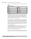
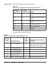
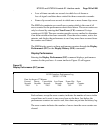
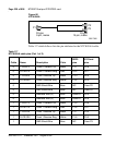
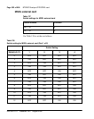
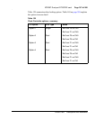
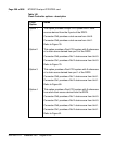
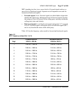
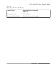
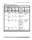
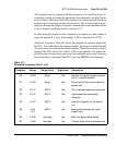
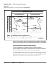
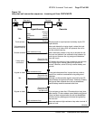
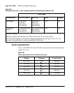
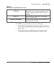
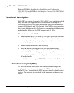
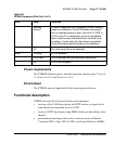
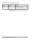
QPC720 Primary Rate Interface card (Part 1 of 2)
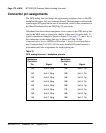
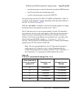
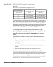
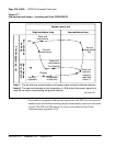
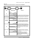
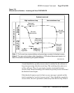
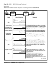
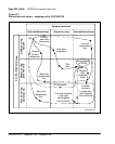
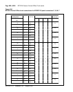
Switch S2 settings To repeater facility To cross-connect point
5 on 0–45 m
(0–150 ft)
0–30 m
(0–100 ft)
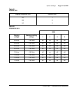
2, 4, 6 on 46–135 m
(151–450 ft)
31–100 m
(101–355 ft)
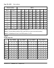
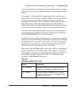
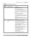
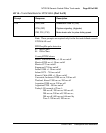
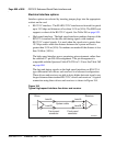
Note 1: All positions on S2 (location B22) are OFF except as shown under the column labeled
“Switch S2 settings.”
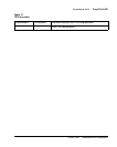
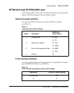
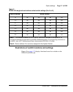
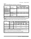
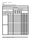
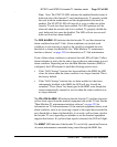
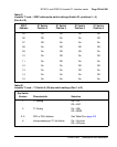
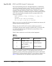
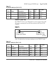
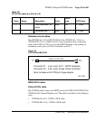
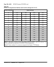
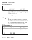
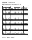
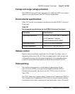
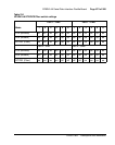
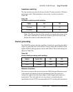
Note 2: Framing format, line encoding, and method of yellow alarm are selectable for both DTI
and PRI in LD17 with the DLOP, LCMT, and YALM prompts. All SW3 switch positions should be
OFF.