


53
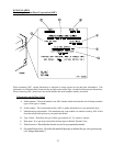
If there is voltage present at the two BS1 terminals, the problem is bad wires or terminations
between the two BS1 terminals and the coil (A1 and A2) terminals.
If there is no voltage across the two BS1 terminals, check for voltage across the two AS1 termi-
nals.
If there is voltage across the two AS1 terminals and there is no voltage between the two BS1
terminals, replace the arc suppressor board.
C. If there is no voltage across the two AS1 terminals, the problem is bad wires or terminations
between the two AS1 terminals and the computer board J7 9-pin connector no. 7 or faulty com-
puter.
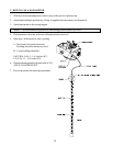
5. Lint Door Condition
NOTE : Make sure main door and lint door are closed. Also, if checking either switch, the plunger must
be depressed.
A. Check L.E.D. input light "LINT" on the component side of the computer. If the light is on, replace
the computer.
B. Check voltage (24VAC) from J7 9-pin connector no. 3 to ground. If voltage is present check no.
4 to ground if voltage is present replace board.
C. If no voltage is present at J7 9-pin connector no. 4 to ground, but voltage is present at no. 3 to
ground. The problem is a bad switch, wires or termination between J7 to J8 and J8 to the lint
switch no. 20 and 21.
D. If no voltage is present at J7 9-pin connector no. 3 to ground, then voltage should not be present
at no. 5 to ground. Replace the board.
6. Main Door Condition
NOTE : Make sure main door and lint door are closed. Also, if checking either switch, the plunger must
be depressed.
A. Check L.E.D. input light "MAIN" on the component side of the computer. If the light is on,
replace the computer.
B. Check voltage (24 VAC) from J7 9-pin connector no. 5 to ground. If voltage is present, check
no. 6 to ground. If voltage is present, replace board.
C. If no voltage is present at J7 9-pin connector no. 6 to ground, but voltage is present at no. 5 to
ground. The problem is a bad switch, bad wires or terminations J7 to J8. J8 to J5 and J5 to main
door switch no. 31 and no. 32.
7. "No Heat" drive and blower motors run, display reads normal (gas models).
A. Check L.E.D. input light "HT1" on the component side of the computer. If the light is on replace
the board.
B. If the L.E.D. input light "HT1" on the component side of the computer is on and there is no voltage
to the HSI module "w" the display will read "BURNER CONTROL FAIL." The problem is bad
wires or terminations between microprocessor and HSI module.
C. If voltage is present on the HSI module "w" to ground. Check voltage at the gas valve if voltage is
present across the two yellow wires at the gas valve and the gas supply is on then the fault is that
of the gas valve.