


18
SECTION V
Servicing
Introduction
ALL electrical and mechanical service or repairs should be made with the electrical power to the dryer
disconnected (power off).
WARNING: PERSONAL INJURY COULD RESULT
The information provided in this section should not be misconstrued as a device for use by an untrained person
making repairs. Service work should be performed by competent technicians in accordance with local, state,
and federal codes. When contacting the factory for assistance, always have the dryer model and serial numbers
available.
CAUTION: Observe
ALL safety precautions displayed on the dryer or specified in this
manual before and while making repairs.
Before considering replacement, make sure that ALL connectors are in place and making proper contact.
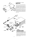
A. Computer Controls
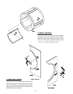
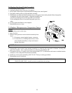
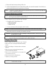
To Replace Input/Output Board Reversing (Prior to February 11, 1998)
1. Discontinue power to the dryer.
2. Disconnect the nine (9) pin connector, six (6) pin connector, four (4) pin connector and a two (2) pin
connector from the computer panel by squeezing the clip on the pin connector and pulling the plug away
from the board.
3. Disconnect the green ground wire from the board
4. Disconnect the ribbon cable assembly from the input/output board reversing.
5. Remove the two (2) screws securing the input/output board to the sheet metal control panel. Remove
the board by pulling the other two corners off the clinch studs.
6. Install new reversing input/output board by reversing this procedure.
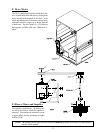
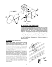
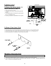
To Replace Display Board
1. Discontinue power to the dryer.
2. Unplug keyboard ribbon from the rear of the computer.
3. Unplug ribbon cable assembly from the rear of the computer.
4. Remove the two (2) screws securing the computer to the computer box door. Remove the computer by
pulling the other two corners off the clinch studs.
5. Install new display by reversing this procedure.
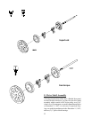
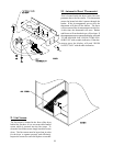
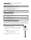
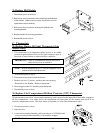
To Replace Computer Board
1. Disconnect power to dryer.
2. Unplug keyboard ribbon from rear of computer.
3. Unplug all wiring harnesses connected to the computer board.
4. Remove the two (2) screws securing the computer to the
computer panel. Remove the computer by pulling the other
two corners off the clinch studs.
5. Install new computer by reversing this procedure.