


43
NOTE: RPM- This routine monitors the timing response from the existing rotational sensor input and
derives a RPM measurement. To display this RPM measurement (press the "ENTER/START"
key once and release, then press the "ENTER/START" key a second time and hold. This will
display the RPM measurement). The rotational sensor must be active for operation of this fea-
ture.
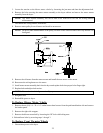
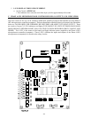
12. CHECK MAIN FUSE- Indicates that the circuit fuse protection which is located on the back side
of the Phase 6 microprocessor controller (computer) the display would read "CHECK MAIN FUSE."
If the display continues after the fuse has been replaced then it is the fault of the Phase 6 microproces-
sor controller (computer).
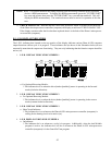
B. L.E.D. DISPLAY INDICATORS
The L.E.D. indicator dots located on the top portion of the display indicates various Phase 6 OPL computer
output functions while a cycle is in progress. These indicator dots (as shown in the illustration below) do not
necessarily mean that the outputs are functioning. They are only indicating that the function output should be
active (on).
1. L.E.D. DISPLAY INDICATOR NUMBER 1
a. For Optional Reversing Models:
1.This indicator dot is on when the drive (basket [tumbler]) motor is operating in the forward
mode (clockwise direction).
2. L.E.D. DISPLAY INDICATOR NUMBER 2
a. For Optional Reversing Models:
1.This indicator dot is on when the drive (basket [tumbler]) motor is operating in the reverse
mode (counterclockwise direction).
3. L.E.D. DISPLAY INDICATOR NUMBER 3
a. Heat Circuit Indicator:
1.This indicator dot is on whenever the Phase 6 OPL microprocessor controller (computer) is
calling for the heating circuit to be active (on).
4. L.E.D DISPLAY INDICATOR NUMBER 4
a. On Indicator:
1.This indicator dot is on whenever a cycle is in progress. Additionally, when the Anti-Wrinkle
program is active, the indicator dot will be on whenever the Phase 6 OPL microprocessor
controller (computer) is in the Guard On Time program.