


5-3
WARNING
Electrical Shock Hazard
Disconnect power before servicing.
Replace all parts and panels before operating.
Failure to do so can result in death or electrical shock.
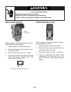
Refer to page 4-4 for the procedure for servic-
ing the door lock/switch assembly.
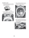
1. Unplug washer or disconnect power.
2. Set the ohmmeter to the R x 1 scale.
3. To test the door switch:
a) Disconnect the connector from the
CCU.
b) Touch the ohmmeter test leads to the
two connector terminals. The meter
should indicate as follows:
Door closed = 0 Ω.
Door open = infinite (open circuit).
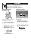
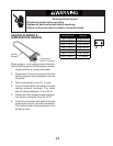
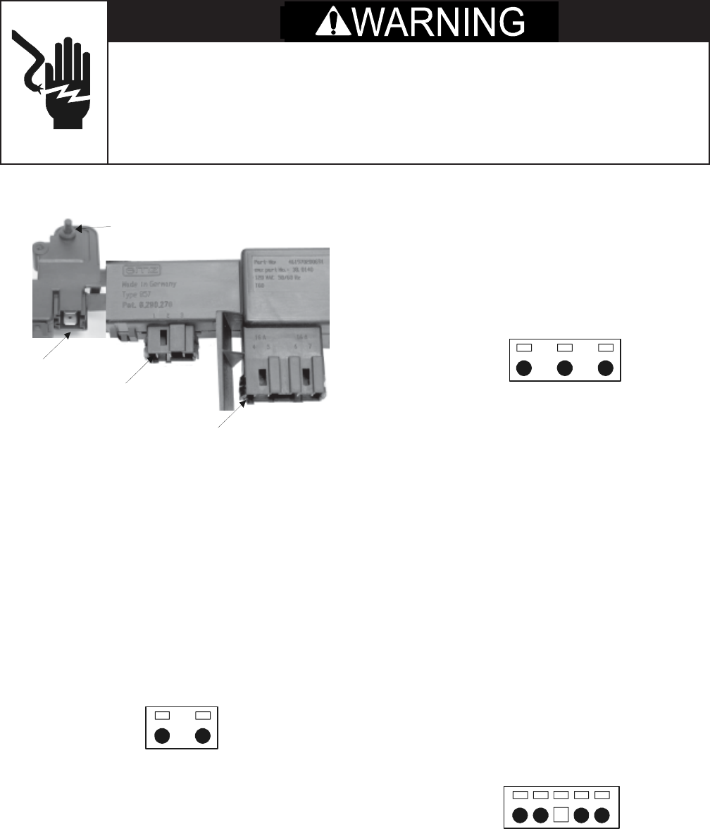
DOOR LOCK/SWITCH ASSEMBLY
Door Switch Actuator
Pins1 - 3
Pins 4 - 7
Door Lock Switches
Pins 1 & 2
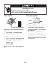
5. To test the door lock main switches:
a) Turn the washer on and select a cycle.
b) Press START and you should hear the
door lock solenoids engage.
c) Unplug the washer from the wall out-
let.
d) Disconnect the door lock main switch
connector from the CCU.
e) Touch the ohmmeter test leads to the
indicated connector terminals. The
meter should indicate as follows:
Main switch 1 at pins 4 and 5 = 0 Ω.
Main switch 2 at pins 6 and 7 = 0 Ω.
c) Reconnect the door lock/unlock sole-
noid connector to the CCU.
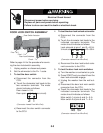
4. To test the door lock/unlock solenoids:
a) Disconnect the connector from the
CCU.
b) Touch the ohmmeter test leads to the
indicated connector terminals. The
meter should indicate as follows:
Lock solenoid at pins 1 and 3 = 60 Ω.
Unlock solenoid at pins 2 and 3 = 60 Ω.
c) Reconnect the door switch connector
to the CCU.
(Connector viewed From Wire End)
(Connector viewed From Wire End)
(Connector viewed From Wire End)
45 67
1 2 3
2 1