


3-4
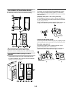
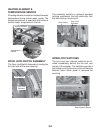
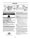
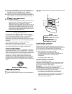
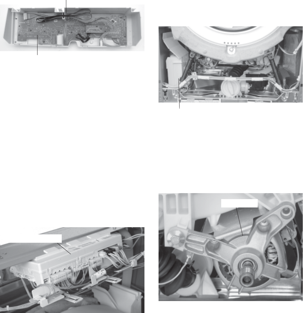
TOUCHPAD/LED ASSEMBLY
The Touchpad/LED Assembly is removed as a
single assembly and is connected to the Cen-
tral Control Unit by a ribbon cable. This assem-
bly contains all of the buttons, LEDs and ribbon
cable and printed circuit boards for the user to
operate the washer. This interfaces the con-
sumer inputs to the Central Control Unit.
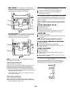
CENTRAL CONTROL UNIT (CCU)
The Central Control Unit is located at the top
rear of the washer and is enclosed in a control
box. There are no serviceable parts inside the
control box. If diagnostic tests indicate any
component of the CCU is defective, the entire
control box must be replaced.
The CCU receives input from the touchpad/
LED assembly and directly controls the dis-
penser, drain pump, water inlet valves, door
locking and unlocking solenoids, and heating
element relay. The CCU monitors the pressure
switch, flowmeter, temperature sensor and door
lock switches.
The CCU sends the customer selection input to
the Motor Control Unit for proper motor opera-
tion.
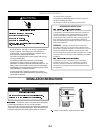
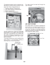
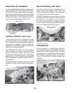
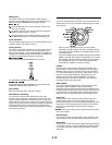
MOTOR CONTROL UNIT (MCU)
The Motor Control Unit is located inside a
plastic control box located in the lower front
corner of the washer cabinet. The control box
is shown with the access door open.
The MCU operates the drive motor at varying
speeds and direction based on inputs received
by the CCU to complete the cycle selected.
The MCU also monitors a tachometer on the
motor to confirm that the drive motor is operat-
ing at the proper speed and direction.
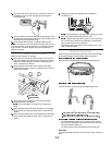
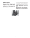
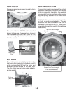
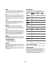
DRIVE MOTOR
The drive motor is a three-phase asynchro-
nous induction type that operates at various
speeds and direction based on input voltages
and frequencies. A tachometer on the motor
shaft sends a feedback signal to the Motor
Control Unit indicating the rotation speed and
direction.
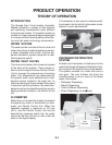
Touchpad/LED
Assembly
Ribbon Cable
Central Control Unit
Motor Control Unit
Drive Motor