4-5
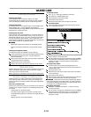
e) Close the washer door.
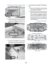
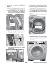
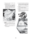
f) Remove the four T-20 hex-head torx
screws from the top and bottom of the
front panel and remove the panel from
the unit.
Top Screws
Bottom Screws
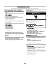
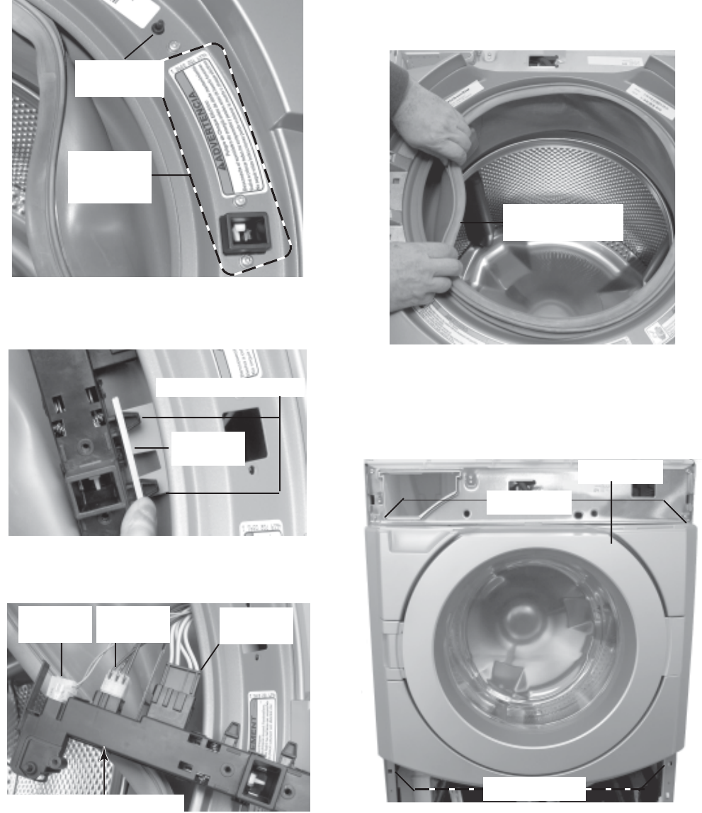
8. To remove the front panel and bellows:
a) Remove the top cover and the console
(see page 4-2 for the procedures).
b) Remove the bellows retaining wire (re-
fer to steps 5 and 6 for the procedure).
c) Pull the bellows off the lip of the front
panel.
d) Remove the door lock/switch assem-
bly (see step 7).
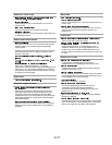
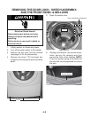
7. To remove the door lock/switch as-
sembly:
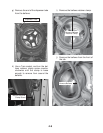
a) Remove the bellows retaining wire (re-
fer to steps 5 and 6 for the procedure).
b) Pull the bellows out and remove the
three T-20 torx screws and flat wash-
ers from the door lock/switch assembly.
c) Push the switch assembly out of the
front panel and then slide the assem-
bly tabs from the connector holder.
d) Disconnect the three wire connectors
from the switch terminals and remove
the assembly.
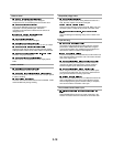
Door Lock
Switches
(2 Screws)
Connector
Holder
2-Wire
Connector
3-Wire
Connector
4-Wire
Connector
Door Lock/Switch Assembly
Remove Bellows
From Panel Lip
Continued on the next page.
Switch Assembly Tabs
Door Switch
(1 Screw)
Front Panel


