


M4557 - Model 9210 Nitriding Controller
SSi Manual SERIES 9210-M4557-Nitriding Page 53 of 53
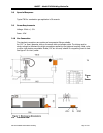
Each gas has an associated solenoid, which turns on to allow flow. The gas solenoids are located
below and behind the Mass Flow Meters. The gas solenoids can be activated manually by turning the
switch on the control panel to HAND for the appropriate gas. The solenoids are also controlled by the 9210
through the events in the recipe and on the manual events menu screen.
Back Pressure Valve
The Back Pressure valve is located behind and to the right of the Flow Head Unit. The Back Pressure valve
is attached to the exhaust of the furnace. The valve provides the necessary back pressure to allow flow
through the Sample Cell. The valve also provides the ability to restrict the outside oxygen from entering
the furnace through the exhaust. During a power outage the Back Pressure valve opens fully to vent all
gases and nitrogen purge out of the furnace.
Differential Pressure Transmitter
The Differential Pressure Transmitter is located to the right and below the Gas Solenoids. The transmitter
sends a signal to the 9210 which controls the amount of back pressure to be applied to the system. It is
critical that no restrictions in the line other than the back pressure valve create the actual pressure. IF the
back pressure valve indicates pressure higher than setpoint and the valve is open this is an indication of a
restriction or water down stream.
Drip Legs
There are three drip legs associated with the flow section. The drip leg valves need to be opened under
the following conditions;
1. Whenever heating up the furnace under air. Heating the furnace under air causes
condensation to build up in the exhaust. The buildup of water in the exhaust lines affects the
back pressure reading. The error in back pressure will affect the reading of the sample and
directly affect dissociation readings.
2. Prior to the addition of ammonia into the furnace. After the heat up of the furnace, when the
furnace is at temperature, the drip legs should be opened briefly to allow any water buildup to
escape.
3. Any time during blowout of lines during cool down cycles and Nitrogen flow.
DO NOT OPEN DRIP LEGS DURING AMMONIA FLOW OR DISASSOCIATED AMMONIA FLOW.
GASES ARE TOXIC AND VERY HAZARDOUS.
The location of the drip legs are as follows:
1. At the bottom of the exhaust line
2. Below the differential pressure transmitter.
3. bottom of the Sample Cell.
Sample Cell Solenoid
The Sample Cell solenoid is energized by event 7 through the program or manual event control.
The solenoid should only be energized when the furnace is up to temperature and the event is turned ON.
Gas is allowed to flow to the sample cell when the solenoid is energized.
Sample Cell Filter
The filter on the inlet side of the Sample Cell Box can become clogged. The part number for a
replacement filter is 37051.