


M4557 - Model 9210 Nitriding Controller
SSi Manual SERIES 9210-M4557-Nitriding Page 52 of 52
ON. The Emergency Nitrogen solenoid is a normally open solenoid and will be open on power failure to the
control panel.
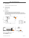
Flow Head Unit
The process gas flow system is located below the sampling The flow head unit is divided into the following
parts; flow control boards, valves, High and Low limits.
Flow Control Boards -
Each gas has an individual flow control board associated with the gas. The
board is located in the flow head unit and communicates to the 9210 controller. The flow control board has
a comm port on it that can be switched between RS-485 and RS-232. The board must be in the RS-485
mode to communicate with the 9210. The RS-232 mode allows for communication directly to a PC running
the configuration software. The RS-232 mode allows for downloading of flow curves and troubleshooting.
On the front of the flow head unit the LED display shows flow of each gas in SCFH. The LED’s on the front
of the unit display the following: Auto/Manual, Alarm, V1, V2.
Auto/Manual -
When the Auto/Manual LED is ON the board is in the Auto Mode being
controlled by the 9210. The switch on the front of the control panel for each gas allows for the board to be
put in Auto, Hand (Manual) or OFF. The LED will be OFF when the switch is in Hand position. The
operator can turn the valve wheel by hand in this condition.
ALM –
This indicator shows when the board is in an Alarm condition. Alams include max
range or high limit switch made.
V1 –
V1 indicates the direction the valve is moving. The LED is OFF when the valve is
closing and ON when the valve is opening.
V2 –
V2 indicates the board is given a Run/Stop command. The LED is OFF when the valve
is receiving a Stop signal. The LED is ON when the valve is being given a Run signal.
Valves -
Each gas has a needle valve attached to a motor. The motor drives the needle valve via a worm
gear. The needle valve shaft has a wheel attached with a set screw that allows the valve to be turned by
hand. If adjusting the wheel by hand unplug the connector from the drive so the 9210 is not trying to
open or close the valve during hand adjustment.
Limit Switches -
Each valve has a limit switch that will not allow the valve to open past a preset limit.
These upper limits need to be set in the field for each gas.
Before setting the upper limit, the
maximum SCFH needs to be known for each flow meter.
Instructions for setting the upper limits are as
follows:
1. Loosen the set screw on the wheel.
2. Send a setpoint to the valve to obtain the maximum flow desired.
3. Allow the valve to settle at the desired flow.
4. Pull the wheel up till the limit switch is activated.
5. Tighten set screw.
6. Repeat for each valve.
7. Drive each valve closed and then open past the max range to test the limit switch. Be
sure to have the event for that specific flow meter turned on under manual events.
Mass Flow Meters
The Mass Flow Meters are located below the Flow Head Unit. The flow meters send a 4-20ma
signal to the flow boards to indicate actual flow. If there is no flow it will trigger a Lo FL alarm. If the flow
meter has reached its maximum, all LED’s will be ON and the last one will be flashing. Each Mass Flow
meter is calibrated for a specific range of flow depending on the gas associated with the meter.
Gas Solenoids