


M4557 - Model 9210 Nitriding Controller
SSi Manual SERIES 9210-M4557-Nitriding Page 51 of 51
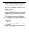
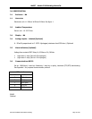
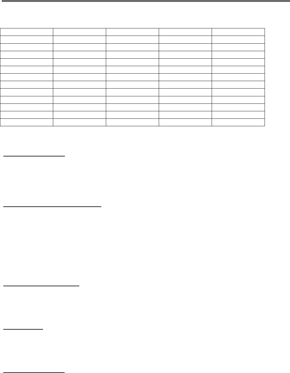
Recipe 61
Step Opcode Temp ATM Options
S1 EVT OUT 1 – OFF
S2 EVT OUT 2- OFF
S3 EVT OUT 3 – OFF
S4 EVT OUT 4 – OFF
S5 EVT OUT 5 – ON
S6 ALARM 1
S7 NO OPT
S8 NO OPT
S9 NO OPT
S10 NO OPT
S11 NO OPT
S12 NO OPT
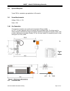
Flow Section
Nitriding Gas Supply
The Nitriding gas supplies enter the flow section from the top. Each gas has a manual shut off valve as
well as a regulator (regulators optional). The regulators are to protect against fluctuations in incoming
supply pressures. The location for each incoming gas inlet is as follows from left to right: Nitrogen,
Ammonia, and Disassociated Ammonia. Pressure regulation should be set between 12 and 20”.
High and Low Pressure Switches
Each gas has a High and Low pressure switch. The location of these switches are just below the manual
valves for the incoming gas. The High Pressure Switch is on top and the Low Pressure Switch is on the
bottom. The switches have green LED indicators to indicate the pressure condition. Example, If the LED
indicator is OFF on the High Pressure switch then the incoming pressure from the supply gas is to high and
the condition generates an audible alarm. Each pressure switch has a dial setting on the front to make
adjustments to the switch. The pressure switches are set by SSi at the time of panel checkout. SSi presets
the regulators for 15” water. The High and Low Pressure switches are set based on this value. Any
questions on the settings please call SSi technical support at 800-666-4330.
Vessel Pressure Switches
Vessel Pressure is the accumulated pressure of all gases flowing through the furnace. The switches for
Vessel Pressure are located to the immediate right of the gas pressure switches. These pressure switches
have LED’s to indicate high and low pressure.
Sample Ports
Each gas has a sampling port below the pressure switches. To take a flow pressure reading using a
manometer, just connect the manometer to the sampling port and turn the manual valve until it is open.
Make sure the incoming supply valve for the gas being checked is also opened.
Emergency Nitrogen
Emergency Nitrogen can be added to the system in the event of an emergency. The operator can initiate
Emergency Nitrogen purge by turning the Emergency Nitrogen switch on the front of the control panel to