


INTRAC-305 FAULT FINDING
© Advantech Wireless INTRAC-305 MANUAL - Issue 3.2 Page 81
7
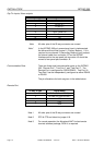
If all the angles are changing the fault is on the Interface
PCB.
wrong angle displayed If the displayed angle changes to be near 0 or 90 it is
probable that one of the two return signal circuits from the
resolver is broken or the resolver itself is faulty.
If the displayed angle changes to any angle other than near
0 or 90 the fault is on the Interface PCB.
angle doesn’t change If the displayed angle doesn’t change when the antenna is
when antenna is moved being driven first ensure that the antenna is actually moving in
the relevant plane. Select Manual Mode and drive the
antenna in the appropriate direction and either check that the
beacon level changes or actually look at the antenna.
If the antenna moves but the displayed angle does not
change the problem is the connection of the resolver to the
antenna.
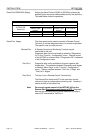
No Antenna Drive Check that the LEDs in the Manual Control keys illuminate
when antenna drive is commanded. If not the fault is on the
Interface PCB.
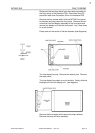
The Motor Controls connector (50-way D-type) on INTRAC
rear panel outputs +12v and ground to for each drive signal.
The +12v and ground levels are switched to the approriate
pins of the connector by relays. One relay switches +12v for
all Az drive commands, another does so for all El drive
commands and a third for Pol drive. The ground level is
switched by changeover relays, one does Az West or East,
another Az Fast or Slow, another El Down or Up, another El
Fast or Slow and another for Pol CCW or CW.
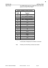
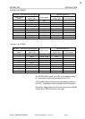
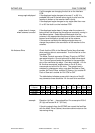
The table below indicates across which two pins of the 50
way connector there should be 12v for each drive condition.
example Elevation Up Fast - there should be 12v across pins 23 & 6
(El Up) and across 24 & 7 (El Fast).
If the drive signals from the INTRAC are correct the fault lies
with the Motor Drive Cabinet, the antenna drive motors or the
intervening wiring.
Direction
& Speed
Az
East
Az
West
Az
Fast
Az
Slow
El
Down
El
Up
El
Fast
El
Slow
Pol
CCw
Pol
Cw
+12 volts
18
19
20
21
22
23
24
25
26
27
Ground
1
2
3
4
5
6
7
8
9
10