


Chapter 3: Installation
3-18 EMM-E6 Installation Guide
3. If the transceiver PWR LED is OFF with the AUI cable connected,
perform the following steps:
a. Check the AUI connections for proper pinouts.
b. Check the cable for continuity.
c. Reconnect the AUI cable to the EMM-E6 and the device.
If the transceiver PWR LED remains OFF, contact Cabletron Systems
Technical Support.
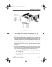
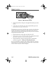
3.5.5 Connecting a 10BASE2 Segment to an EPIM-C
To connect a thin coaxial cable segment to an EPIM-C perform the
following steps:
Before attaching a male BNC connector to a female BNC barrel
connector or terminator, look into the end of the connector to verify that
the gold contact pin is present and centered. Any bent or broken pins may
not connect properly and should be replaced.
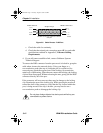
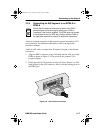
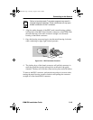
1. Set the Internal Termination (TERM) switch, located to the right of the
port and labeled TERM, to one of the following positions:
a. The ON position ( ) to internally terminate the thin coaxial cable
segment at the port. Thin coaxial cable segments may be directly
connected to the port.
b. The OFF position ( ) to not internally terminate the thin coaxial
cable segment at the port. Segments may only be connected
through T-connectors which are connected to properly terminated
segments on both ends.
NOTE
For proper operation, the EPIM-C module to be configured for
use in the EMM-E6 module must be of EPIM board revision 05
or greater. Board revision numbers are found following the part
number printed on the Printed Circuit Board of the EPIM.
ICH1Book Page 18 Tuesday, August 6, 1996 3:06 PM