


Chapter 3: Installation
3-12 EMM-E6 Installation Guide
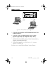
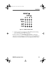
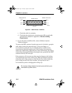
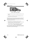
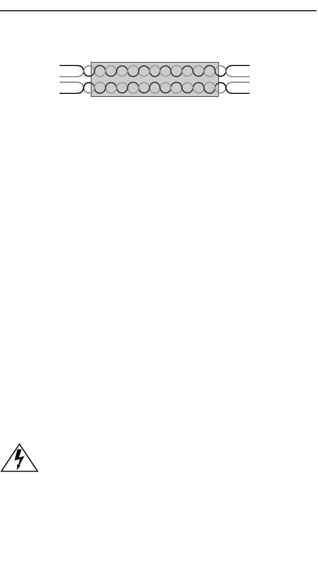
Figure 3-6 Cable Pinouts - RJ45 Port
c. Check the cable for continuity.
d. Check that the twisted pair connection meets dB loss and cable
specifications outlined in Appendix C, Ethernet Cabling
Requirements.
4. If you still cannot establish a link, contact Cabletron Systems
Technical Support.
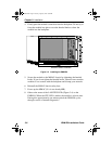
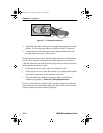
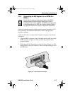
To remove the RJ45 connector from the port once it is locked in, grasp the
cable where it enters the network device. Using your finger or a
non-conductive probe (the cap of a ballpoint pen is a useful tool for
recessed ports) pinch the exposed arm of the locking clip towards the
main body of the housing. When the arm contacts the housing, the locking
clip has been disengaged. Without releasing the arm, gently pull the RJ45
connector directly out of the port.
If the connector will not come out, there may be damage to the locking
clip. Examine the arm of the locking clip. While pressing the arm back
toward the shell of the connector, verify that the clip, located within the
port, is being moved. If the clip is broken, you may need to use a
non-conductive probe to disengage the locking clip.
Do not place foreign objects into device ports while they are
connected to a power source.
Straight-Through
RX+/RX- and TX+/TX- must share a common
color pair
10BASE-T Device PortEPIM-T RJ45 Port
1
2
3
6
Tx+
Tx-
Rx-
Rx+
1
2
3
6
Rx-
Rx+
Tx+
Tx-
1926n09
ICH1Book Page 12 Tuesday, August 6, 1996 3:06 PM