


450260-1 www.amdry.com 37
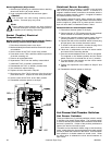
6. Check the position of the drain plug and the breather
plug.
7. Check the turnbuckle mount pad on the gear reducer
for the correct application.
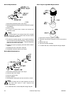
8. Install the new gear (speed) reducer on the drive shaft
along with the taper lock bushing, the pillow block
bearing (setscrews in the pillow block bearing face the
end of the drive shaft), the taper lock bushing, and the
drive wheels.
9. Reinstall the drive shaft into the dryer.
10. Secure the gear reducer to the drive shaft by reinstalling
the three (3) bolts into the taper lock bushing and tighten
evenly for proper mounting.
11. Repeat Step #12 to reinstall the other taper lock bushing.
12. Reinstall the bolt into the turnbuckle and mounting
bracket.
13. Reinstall V-belts and tighten turnbuckle.
14. Prior to operating new gear (speed) reducer, fill with
1.48 quarts (1.4 liters) of SAE 90 gear oil.
Impor tant
Do not overtighten turnbuckle.
15. Mount the pillow block bearings onto the mounting pads
(using the bolts that were removed). Do not tighten.
16. Tighten the taper lock bushing into the drive wheels.
17. Tighten the adjustment bolts until the basket (tumbler)
is centered.
Impor tant
Remove the wooden blocks that were inserted under
the basket (tumbler).
18. Tighten the bolts on the pillow block bearings.
Note
Verify correct mounting position of the gear reducer.
Make the necessary corrections and/or adjustments
to the gear reducer for proper mounting. Changing
the drain plug, breather plug, as well as the turnbuckle
mounting pad may be required.
Inspect all of the work performed checking for security of
parts and proper alignment.
19. Reestablish electrical power to the dryer.
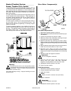
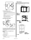
Retaining Wheel Components
Retaining Wheel Cover Panel Removal
1. Discontinue electrical power to the dryer.
2. Remove the side front panel to access the two (2) front
retaining wheels and/or the rear panel to access the
two (2) rear retaining wheels.
Note
The lower front retaining wheel does not have a cover.
The guard panel must be removed from the dryer to
access the rear bottom panel.
3. Remove the bolts from the guard panel to gain access
to the rear retaining wheel.
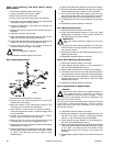
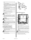
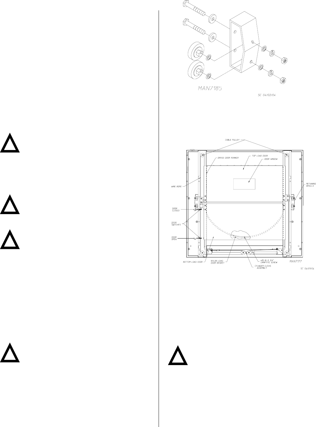
Retaining Wheel(s) Replacement
1. Discontinue electrical power to the dryer.
2. Remove the front side cover.
3. Remove the hardware (i.e., bolt, lock washer, and flat
washer) from the hex nut and weld nut on the wheel
mount.
4. Install the new retaining wheel. Reinstall the lock
washer then the flat washer onto the bolt and insert into
lower mount hole through the retaining wheel and
through the hex nut, then into the weld nut and snug up
the bolt.
Warning
All service and troubleshooting should be performed
by a qualified professional or service agency.
While making adjustments, observe all safety
precautions displayed on the dryer or specified in this manual.
5. Reinstall cover removed in Step #2.
6. Reestablish electrical power to the dryer.
!
!
!
!
!