


14 American Dryer Corp. 450260-1
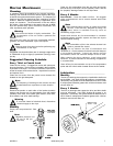
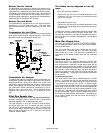
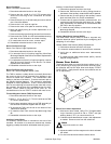
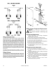
Burner Fan Motor
Burner Fan Motor Replacement
1. Discontinue electrical service to the dryer.
2. Remove the four (4) #8-18 x 7/16" TEK screws which
secure the inlet ring to the combustion air blower
housing.
3. Remove the two (2) 1/2-20 left hand jam nuts as well as
the 1/2-inch flat washer.
4. Remove the 6-1/4" squirrel cage fan.
5. Remove the motor cover plate to reveal the wiring.
6. Mark and identify wiring for correct replacement on to
the new motor.
7. Remove the cord grip and wiring harness from the motor.
8. Remove the four (4) 3/8-16 x 3/4" hex head bolts securing
the motor to the combustion air blower housing.
9. To install new burner fan motor, reverse steps.
10. Reestablish electrical service to the dryer.
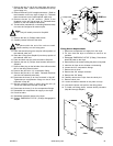
Burner Fan Squirrel Cage
Burner Fan Squirrel Cage Replacement
1. Discontinue electrical service to the dryer.
2. For removal of the 6-1/4" squirrel cage fan, follow Step
#2 through Step #4 of the Burner Fan Motor Replacement
instructions above.
3. For replacement of new 6-1/4" squirrel cage fan, reverse
Step #4 through Step #2 of the Burner Fan Motor
Replacement instructions.
4. Reestablish electrical service to the dryer.
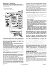
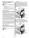
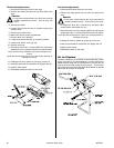
Burner Fan Electrical Components
Burner Fan Thermal Magnetic Starter (TMS)
The TMS is used as a safety device to manually disconnect
the motor so that it will be protected from damage in the
event of a locked rotor condition. The overload has a dial
setting on the face of the device. To set the overload, refer to
the specific electrical diagram. The overload is specifically
designed for motor applications. It has a current curve built
into it so the initial high current draw by the motor will not trip
the overload. On the face of the overload are two (2) push-
buttons; "START" (Black or Tan) and "STOP" (Red - 0). The
overload has to be in the "START" mode for the motor to run.
Thermal Magnetic Starter (TMS) Replacement
1. Discontinue electrical service to the dryer.
2. Mark L1, L2, L3, and T1, T2, T3 on the wires to the TMS
for correct replacements.
3. Set the amp (amphere) rating on the TMS according to
the electrical schematic supplied with the dryer.
4. To remove the TMS, pull the tab on the bottom of the
TMS and lift upwards.
5. To install the new TMS, reverse Step #4 through Step
#2.
6. Reestablish electrical service to the dryer.
Auxiliary Contact Block
The auxiliary contact block is mounted on the side of the
overload. Its function is to sense an overload trip, thereby
triggering a safety fault which will disable the drying cycle.
Auxiliary Contact Block Replacement
1. Discontinue electrical service to the dryer.
2. Remove the TMS from the din rail by pulling the tab on
the bottom of the auxiliary contact block and lift upwards.
3. Remove the two (2) wires going to the auxiliary contact
block and label them for correct reinstallation.
4. There are two (2) types of auxiliary contact blocks: one
type has a screw and the other type has a clip. In either
type, disassembly and assembly is recommended with
the TMS in the stop position.
5. To install the new auxiliary contact block, reverse Step
#4 through Step #2.
6. Reestablish electrical service to the dryer.
Varistor (Metal Oxide Varistor [MOV])
The metal oxide varistor (MOV) is used to suppress any
inductive electrical spikes produced by the energizing and
collapsing of coil voltage.
Varistor (Metal Oxide Varistor [MOV]) Replacement
1. Discontinue electrical service to the dryer.
2. Loosen the screws marked A1 and A2 on the contactor.
3. Verify that no additional wires were inadvertently
removed.
4. To install the new metal oxide varistor (MOV), reverse
Step #3 through Step #1.
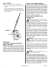
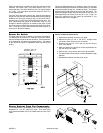
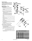
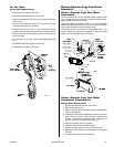
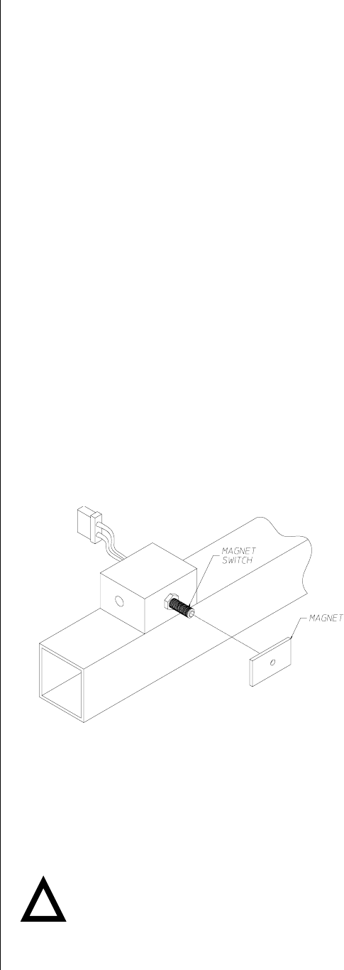
Burner Door Switch
The burner door switch is a part of the dryer's safety circuit. If
at any time during a drying cycle the burner doors are open,
the controller will shut the dryer down and display "FRONT
DOOR OPEN." (Verify that the burner door switches are not
out of adjustment.)
Burner Door Switch Adjustment
1. With burner doors closed, verify if PLC (Programmable
Logic Controller) Input #8 is ON or FDRC red light
emitting diode (L.E.D.) on control board is on.
2. If indicator shows that the door is open , then adjustment
is needed. Remove cover from the switch box.
Note
Adjust one switch at a time.
3. Adjust the switch until the magnet on the door activates
the switch.
4. Put the cover back and close the burner doors.
MAN7175
SC 04/1/04
!