


12 American Dryer Corp. 450260-1
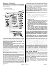
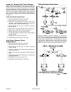
Sequence of Operation
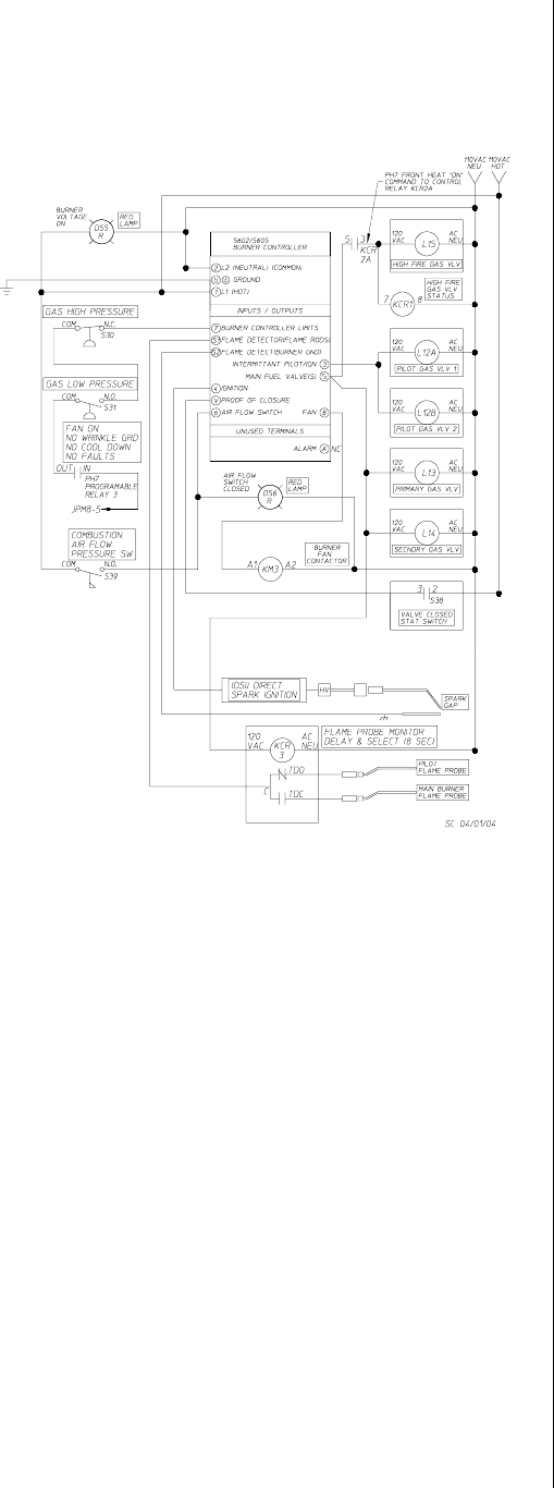
With dryer power on, a 120 volt signal is sent to terminal #1
and terminal #2 of the burner controller module (BCM). A
power indicator light has been added to the controller base
for troubleshooting.
Drying cycle is started
Dryer computer calls for heat.
The BCM checks that all of the dryers safety circuits are closed
(terminal #7 of the BCM). If this is the case, then the green
operating interlocks light emitting diode (L.E.D.) on the BCM
will light. If a safety switch is open, the green L.E.D. will not
light, and the red SYSTEM UNSAFE L.E.D. will light. The
ignition sequence will stop.
If all safety switches are closed, the BCM will start the burner
fan motor (BCM terminal #8).
The BCM waits 10-seconds to allow the blower motor to get
up to speed, and then checks that the burner fan combustion
air switch (BCM terminal #6) circuit is closed. If this circuit is
open during the drying cycle, the Air Failure L.E.D. will light.
The gas valve will close, and a HEATER FAULT message
will be displayed.
In order to prevent this air switch from being jumped out, the
BCM checks to insure that this circuit is open prior to start-up,
then SYSTEM UNSAFE L.E.D. will light.
If the air flow switch closes after the burner fan is turned on,
the pilot solenoid valve (BCM terminal #3) is opened for ten
(10) seconds, and a spark is produced (BCM terminal #4) by
the burner spark plug, igniting the pilot flame.
The flame rod, which extends into the pilot flame, has
300 VAC on it from the BCM (terminal #S1). The flame lets
the current flow from the flame rod to ground, which is then
converted to 3 to 11 volts DC by the BCM. The flame signal
L.E.D. on the BCM lights up. Once the call for heat opens the
main valve, the flame rod circuit is switched to the opposite
side of the burner to confirm that the flame is across the
entire burner.
The spark plug will turn off 1.5-seconds after the pilot flame
is detected. If the pilot flame should fail during the
10-seconds period that the pilot solenoid is open. The BCM
will reenergize the spark. If the pilot flame is not established
at the end of this 10-second period, the system will lock out
and the FLAME FAILURE L.E.D. will light.
The 10-second period when the pilot solenoid opens and a
spark is produced is called the trial-for-ignition (TFI) time. It
is selected at either 5-seconds or 10-seconds by a dip switch
located on the back cover of the BCM.
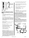
The 3 volt DC to 11 volt DC signal from the flame rod to the
BCM can be measured by:
Closing the manual shutoff valve in the main gas line to
the burner. Leave the pilot manual valve open.
Push the Test and Reset button on the cover of the BCM
in to the test position.
Start a drying cycle
The BCM will halt the ignition sequence after the pilot is
ignited. The pilot flame should be about the size of a
tennis ball and should make the flame cord red hot.
Insert the positive probe of a DC Volt Meter in to the flame
signal port on the cover of the BCM. Connect the negative
probe to ground.
If signal is less than 3 volts DC, then the pilot may be too
small or too large, there may be a wiring connection
between the flame rod and BCM, the flame rod may be
dirty, (wash it with soap and water) or defective, or the
grounding may be faulty.
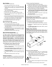
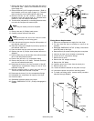
Once the flame probe signal is detected by the BCM, it waits
5-seconds to allow the pilot to stabilize and then opens the
main motorized gas valves (terminal #5 on the BCM) in
sequence.
The lower valve opens first. Upon full opening, its external
switch closes, enabling the second motorized valve to open
and full flame to be achieved.
At this time an 8-second delay timer is activated. After
8-seconds the flame sensor is switched from the pilot to the
main flame sensor on the opposite side of the burner box.
If flame failure occurs within 35-seconds, the system will
lock out and the FLAME FAILURE pilot will light.
Once main flame is established, the burner will remain in
the full fire mode until the drying set point temperature has
been reached. At this point, the dryer computer will cycle the
top motorized gas valve closed the position. The OFF mode
will be maintained until the dryers temperature falls below
the drying set point temperature. The motorized valve will
then be returned to the full fire position. The ON/OFF motor of
the motorized valve, it moves to the full fire position. OFF is
achieved when no voltage is applied to the motorized valve.
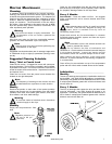
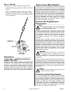
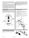
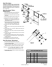
Gas Burner Start-Up
New gas lines are filled with air and must be purged before
the burner will light. To do this close the upper manual
shutoff valve, but leave the pilot line shutoff open. Push in the
test and reset button on the cover of the BCM. This will freeze
the ignition sequence when the pilot flame ignites. This
allows time to examine the pilot flame, and measure the
flame rod signal to the BCM.
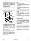
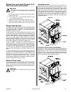
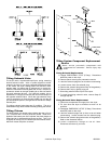
Connect a pressure gauge or water tube to the pilot gas
pressure tap. Start the dryer. Follow the ignition process by
referring to the Sequence of Operation section of this
manual.
MAN7174